


 160 / 352

156
The results of the tensile tests of the welded joint are shown in Table 9. The
specimens started to yield at about 700 MPa and fractured in the WM, indicating that
strength under matching of the welded joint was obtained (compare Table 4.).
The results of guided bend tests according to EN 910 (Welded butt joints in metallic
materials - Bend test) are given in Table 10, as bending angle and fracture initiation
location. They show a limited deformation capacity of the welded joints. Cracks occurred
at the fusion line and in the WM for specimens bent around the face side (i.e. the side of
pass 6, Figs. 11 and 12). Better results were obtained for specimens bent around the weld
root, since the weld face side was wider and did not contain a critical region of the HAZ
with a dominant coarse-grained microstructure, close to the fusion line.
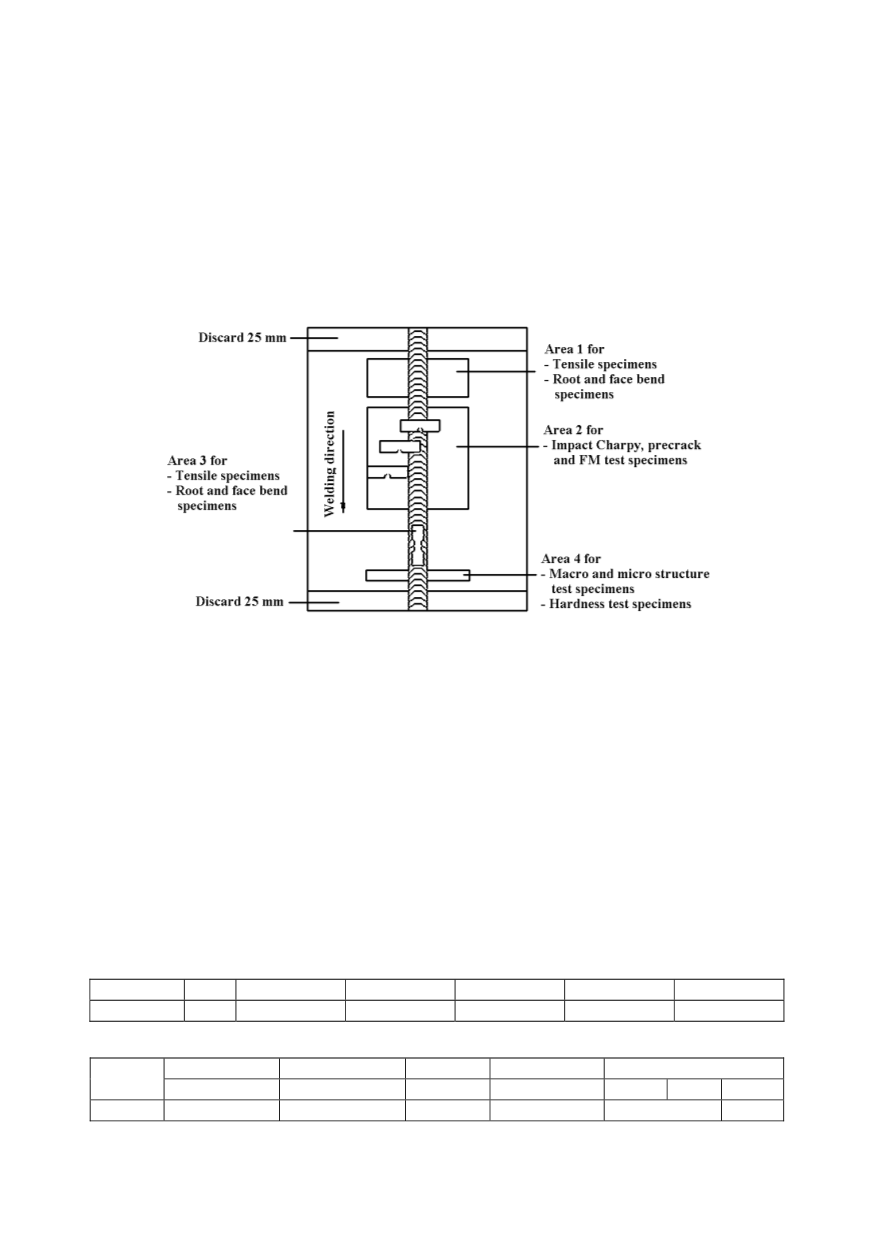
Figure 12: Welding direction and specimen positions in the sample plate
Extended instrumented Charpy V-notched specimens tests of the WM and HAZ were
performed according to ASTM E23-86 at different temperatures. The position of the V-
notch in the specimen, determined following Fig. 8, is presented in Fig. 15. The results in
Table 11 present the total impact energy and the parts for crack initiation and propa-
gation. The maximum load is accepted for the calculation of the crack initiation energy.
Comparison with the results for the BM (Table 4) show that the WM has lower impact
energy at all temperatures, with a higher transition temperature. Although the energy
values for the HAZ are acceptable, the significant scatter of the results required a detailed
analysis of the effect of microstructure.
Coarse-grained regions (Fig. 10) contributed to the reduced impact toughness of some
specimens in Table 11. The effect of low toughness is localized by multipass welding,
producing regions of lower impact toughness as narrow segments in the HAZ, surrounded
by metal of higher toughness, in which crack growth will be arrested.
Table 6: Chemical composition of the weld metal, %
Electrode
C
Mn
Si
Cr
Ni
Mo
EVB 75
0.06
1.65
0.3
0.55
2.0
0.35
Table 7: Mechanical properties of the weld metal according to specification
Yield stress
Tensile strength Elongation Contraction
Impact energy, J
Electrode
R
p0.2
, MPa
R
m
, MPa
A
, %
Z
, %
+20°C -40°C -60°C
EVB 75
710-770
770-830
18-20
110-140
50-80
35-65