


 156 / 352

152
tion for base metal specimen. For instance, in a girth weld of a pipe, the long direction of
the weld is the pipe hoop direction, not the longitudinal or axial direction of the pipe.
Fracture toughness testing of HAZ presents particular problem, because several dif-
ferent microstructures can cluster in the HAZ, based on the different heating histories in
different locations from the welding. A fracture toughness measured in the HAZ is likely
to be affected both by the properties of the several HAZ microstructures that the crack tip
passes through and by the properties of the adjacent WM and BM.
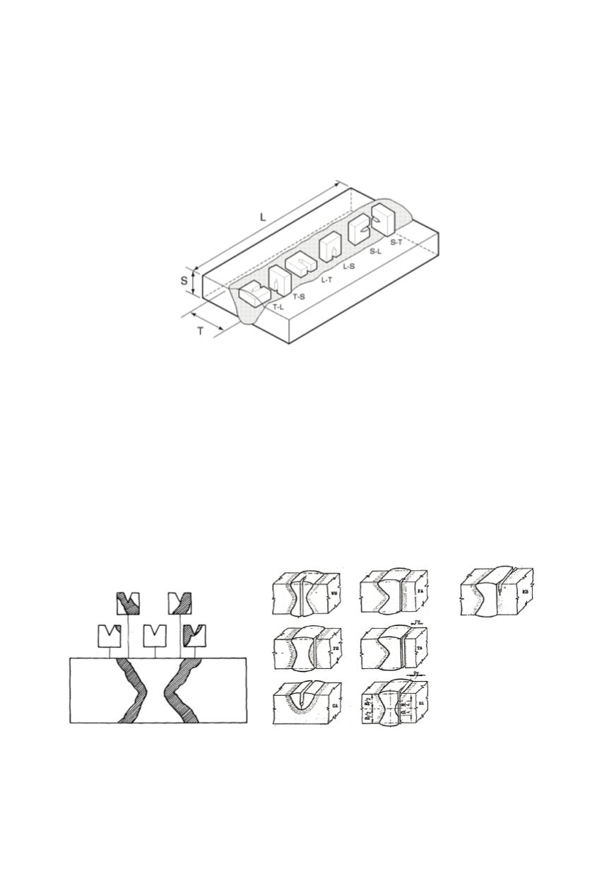
Figure 7: Orientations of toughness specimens relative to weld. L - longitudinal direction; T - long
transverse direction (weld width); S - short transverse direction (weld thickness). In the two-letter
code, the first letter designates the direction normal to the crack plane, and the second letter
designates the expected direction of the crack plane /12/
Fracture initiation toughness is measured using the stress intensity factor,
K
, the
J
-
integral,
J
, or the crack tip opening displacement (CTOD). All these parameters are
applied to welded joints. CTOD measurements are specified in welded regions rather than
in base metal, since this test was originally developed for welded joint. Conversions
between
K
,
J
, and CTOD can be performed but with limited accuracy.
Fracture toughness testing of welds may require precise positioning of the notch to test
the microstructure of interest (Fig. 8). Testing of welds may also require some modifica-
tion of the test specimen. Anyhow, the choice of particular specimen geometry depends
on testing purpose and requirements.
Figure 8: Typical notch positions in fracture mechanics specimens of welded joint
Significant differences in toughness also may be attributed to differences in the frac-
ture criteria. Data obtained as the CTOD or
J
integral evaluate the fracture toughness of
ductile materials after significant crack extension, in plastic range. Consequently, the