


 164 / 352

160
crack tip can be located more accurately in the same microstructure, but an X-shaped
sample was selected because it describes the crack response in a real structure better.
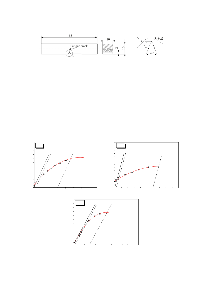
Figure 16: Pre-cracked three-point bend specimen SE (B) applied for impact and J integral testing
It should be mentioned that the specified requirements regarding strength, ductility
and toughness were fulfilled. However, an additional consideration of the significantly
reduced impact energy of the WM was necessary. It was argued that, if required, an elect-
rode of better toughness, with a higher Ni content, producing a lower nil ductility tran-
sition temperature, could be applied. However, the HAZ behaviour still requires analysis,
bearing in mind that the application of a better electrode would not affect the microstruc-
ture and properties of the HAZ. The microstructure of the HAZ region where a crack was
initiated can be revealed on a broken specimen, after the test.
Fracture mechanics tests performed with the
J
-integral enabled the picture of the crack
behaviour of the constituents of welded joints to be completed. Single Edge (SE), three-
point bend (B) specimen, pre-cracked in the BM, WM and HAZ, (Fig. 16), were tested in
a support span,
S
=
40 mm, following the single specimen compliance technique accor-
ding to ASTM E1737. Typical
J
-
Δ
a
curves, obtained for the BM, WM and HAZ in the
tests, are presented in Fig. 17.
0
1
2
3
4
0
200
400
600
800
1000
J
Ic
BM-1
J - Integral, kJ/m
2
J
Ic
= 117,4 kJ/m
2
Crack Extension,
Δ
a, mm
a)
0,0
0,5
1,0
1,5
2,0
2,5
0
50
100
150
200
250
300
350
400
J
Ic
WM-1
J - Integral, kJ/m
2
J
Ic
= 67,6 kJ/m
2
Crack Extension,
Δ
a, mm
b)
0
1
2
3
4
5
6
0
200
400
600
800
1000
J
Ic
HAZ-1
J - Integral, kJ/m
2
J
Ic
= 102,2 kJ/m
2
Crack Extension,
Δ
a, mm
c)
Figure 17:
J
-
Δ
a
diagrams (crack resistance curves) for SE(B) specimens:
a) BM-1, b) WM-1 and c) HAZ-1.