


 155 / 352

151
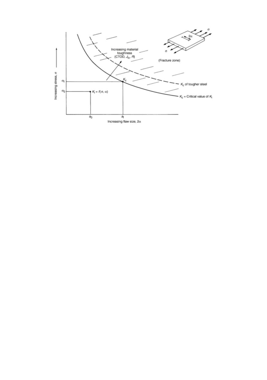
Figure 6: Relationship among stress, flaw size, and material toughness
/
12
/
As discussed, crack resistance can be evaluated by different fracture mechanics para-
meters. Three of them are in general use: the stress intensity factor
K
, the crack opening
displacement (COD),
and the
J
integral. Their critical values: plane strain fracture tough-
ness
K
Ic
, critical COD (
δ
c
), and
J
Ic
, a measure of fracture toughness, can be used as
material properties of homogeneous materials. However, there are many problems in
testing and evaluation of results for welded joints connected with the properties of the
WM and the heterogeneous microstructure of the HAZ.
5. FRACTURE MECHANIC TESTING OF WELDED JOINTS
The weld metal and adjacent HAZ have heterogeneous microstructures, with regions
of different strength and toughness, that affects fracture behaviour. Welding residual
stresses have also to be taken into account in fracture consideration. This situation makes
fracture testing of welded joints to be complex. Fracture testing, using slow loading and
precracked specimen, allows determination of only the crack initiation portion of the frac-
ture toughness. Charpy testing determines a combination of crack initiation, propagation
and arrest properties. Fracture initiation testing of welded joints thus is even more sen-
sitive to the local microstructure ahead the crack tip than Charpy tests are to the micro-
structure at the notch. Heterogeneity also causes welds to be particularly sensitive to the
rules for data interpretation for fracture initiation tests. Fatigue precracks are less likely to
be straight in a heterogeneous material. Tests may have multiple events of crack initiation
and arrest in local areas (“pop-ins”). Different strengths may cause validity criteria based
on yield strength and specimen size to give ambiguous results. Each of these issues must
be accounted for in a test protocol appropriate to welds. Fracture toughness specimens
can be taken from welded joints in several orientations as shown for compact tension
specimens in Fig. 7. These orientations can be designated by two-letters: first letter is the
direction normal to the crack plane, while the second letter is the direction in which the
crack will propagate. The letter choices are L - longitudinal direction; T - long transverse
direction (the weld width direction); and S -, short transverse direction (the through
thickness direction). Care should be taken that the orientation letters describe the weld
area, because different combinations of these letters may be applied to the same orienta-