


 152 / 352

148
severe than embedded one of the same size and similar shape. As stress raisers, the
discontinuities affect fatigue and brittle fracture behaviour in their immediate vicinity.
Cracks are the main problem for structural integrity of welded structures, and fracture
mechanics is inevitable tool, including testing of cracked specimens.
Cracks in welds can occur in welding manufacturing, or during service.
The cracking associated with the welding process can occur in deposited weld metal in
the form of hydrogen attack, gas porosity and solidification cracks, at the fusion line like
liquation cracks, HAZ burning or hot tearing and in HAZ in the form of lamellar tearing,
cold or hydrogen induced cracks and reheat cracking (which can also occur in WM).
The most complex and severe are solidification and liquation cracks, lamellar tearing,
cold and reheat cracks. The basis for discussion of the cracking mechanisms in different cases is
the crack
resistance of a material and howwelding can affect this property /1,5/.
In-service cracks are produced by the effect of applied load, environment, vibration or
service thermal cycling.
3. STRESS CONCENTRATION
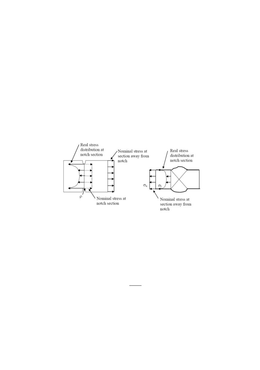
Typical stress concentrations due to notches are shown in Fig. 4.
Figure 4: Stress concentrations at notches: plate with edge notches (left): butt welded joint (right)
In a plate with two edge notches, symmetrically disposed, the stress will increase
slightly due to cross section reduction by notches, and much more by stress distribution
caused by the local disturbance, dependent on the notch radius size
ρ
. When overloaded,
cracks might appear in the root of notches. Similarly, in butt welded joint the reduction of
cross section affects slightly, and much more is expressed the stress concentration by
WM overfill at the transition between the BM and WM. These effects can be described
by the stress concentration factor,
k
t
, expressed as the ratio of the maximum local stress,
σ
max
, and the nominal stress,
σ
, in remote cross section:
max
t
k
σ
σ
=
(1)
The maximum stress for a given planar discontinuity occurs when the plane of the
discontinuity is perpendicular to the direction of the tensile stress and approaches zero as
the plane of the discontinuity becomes parallel to it. The stress increase caused by a sur-
face discontinuity is about twice compared to an embedded discontinuity of equal size
and shape. The stress increase due to planar discontinuity whose plane is perpendicular to
the direction of the tensile stress is higher compared to a volumetric discontinuity of
equal planar size and shape projected.