


 30 / 352

26
2
1
6
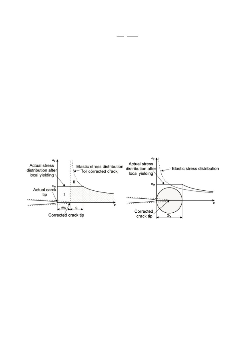
eff
y
YS
K
r
π σ
⎛
⎞
= ⎜
⎟
⎝
⎠
(12)
Calculation of
K
eff
is iterative process that, however, very fast leads to the end values.
The correction is in reality also dependent on material hardening (
n
) and geometry.
In fact, calculation process in LEFM is the same, independent on plane stress or strain
conditions (or between), but the toughness values (that must be evaluated experimentally)
are higher if the conditions are not plane strain. This increase is accompanied with
sometimes large errors, and it is better to use the
K
Ic
values. Methods of LEFM meet the
limits if the stress is higher than the half of yield strength. It should be recognize that the
calculation results are more and more on the unsafe side.
Corresponding relationships and mechanisms can be explained graphically in a simple
way using stress-strain diagram for specimen with the crack (Fig. 8). It is not difficult to
note that because of additional plastic deformations the amount of energy spent is larger.
Physical mechanisms of energy dissipation are based on plastic deformation in the
vicinity of crack tip for metals, micro cracks for ceramics, fibre pull-out for composites
and even on the basis of material heating and/or on all that. For that, convincing energy
ends to be only crack surface energy
G = dWdA
as in the case of LEFM conditions. In
plastic deformations, as known, not only crack tip but also the volume near to the tip or
even near to the all net section take part, and this must be considered (
dWdV
).
Figure 7. Irwin’s correction for the plastic zone
As already accentuated, introduced energy is not only spent on crack growth and
fracture. Total energy after loading to the point (P, Fig. 8) corresponds to the area under
the curved (OPS). The energy amount
(dWdV)
p
spent for the plastic deformation become
visible only after unloading, in which the remain recoverable part of energy is released
(dWdV),
that is lower than the total energy. It corresponds to the triangle UPS. It is to
note that unloading path slope of crack extension differs from the initial one. This appears
as the consequence of reduced stiffness due to the net section area reduction. At failure,
assumed in point F, only the recoverable energy is available and, therefore, relevant as the
measure of the failure resistance. It is directly related to the
J
-integral and
G
. However,
this energy cannot be measured in this way, because the specimen is broken.
In LEFM conditions energy release rate
G
is proportional to
K,
as given in Eq. (3).
This is not valid for ductile materials, and in EPFM other parameters are necessary.
There are two main development branches in EPFM: crack tip opening displacement
(CTOD,
δ
), popular in Great Britain and Europe, and
J
-integral, from the beginning