


 25 / 352

21
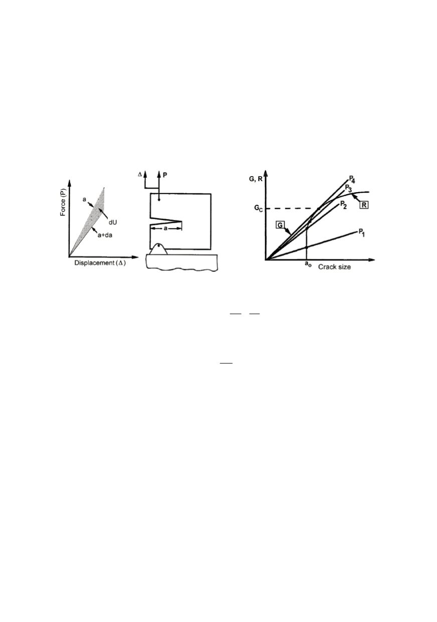
If the driving force
G
is larger than material resistance
R
, the crack growth becomes
unstable. If
G = R
the crack growth can be stable or unstable, that depends on material
and loading configuration, i.e. the way how
G
changes with the crack growth. This
behaviour is described using so called resistance curve (
R
-curve, Fig. 2). The driving
force is presented by a series of
G
versus crack length lines for various load levels. Most
materials have the resistance curve
R
that grows depending on the crack size increase. In
this case, up the loading increase at to the
P
2
level nothing happens, because the material
resistance is larger than the driving force. Only when the loading reaches
P
3
level, the
crack grows for a small amount in accordance to the resistance curve curvature. When the
load reaches
P
4
the unstable situation is established. Because the material resistance is not
sufficient to prevent it, the crack continuously grows, frequently up to final fracture.
Figure 1. Condition for crack growth
Figure 2. Scheme of (un)stable crack growth
In accordance to it one can write:
and
dG dR
G R
da da
=
≤
(2)
At the same time, Irwin showed that for these conditions the equivalent relationship
exists between energy and stress intensity factor
K
for linear elastic materials.
2
'
KG
E
=
(3)
where
E' = E
(Young’s modulus) for plane stress and
E’ = E/(l -
v
2
)
for plane strain;
ν
is
Poisson’s ratio. Anyhow, the stress intensity approach is commonly applied in LEFM.
2.2. Elastic-plastic features of the material
Inelastic strains appear in the material on the basis of dislocations. Inelastic deforma-
tions are of irreversible character. The rules based on the classic plasticity theory decom-
pose total deformation to elastic and plastic parts with corresponding relationship for each
of them. The total strain is the sum of its elastic and plastic components:
ε
=
ε
e
+
ε
p
(4)
Classic plasticity theory is based on following elements:
–
A yield surface defining elastic limit of a material in a multiaxial stress state that
defines if the body will react in elastic or plastic way (Fig. 3).
–
A hardening rule that defines material behaviour during yielding, i.e. the way in which
the resistance to the plastic strain grows together with inelastic strains.
–
A flow rule defining the magnitude and direction of the plastic strain development.
–
Elastic unloading criteria that models irreversible features of the body.