


 33 / 352

29
is possible, even though the effective
K
value does not have any connection with the
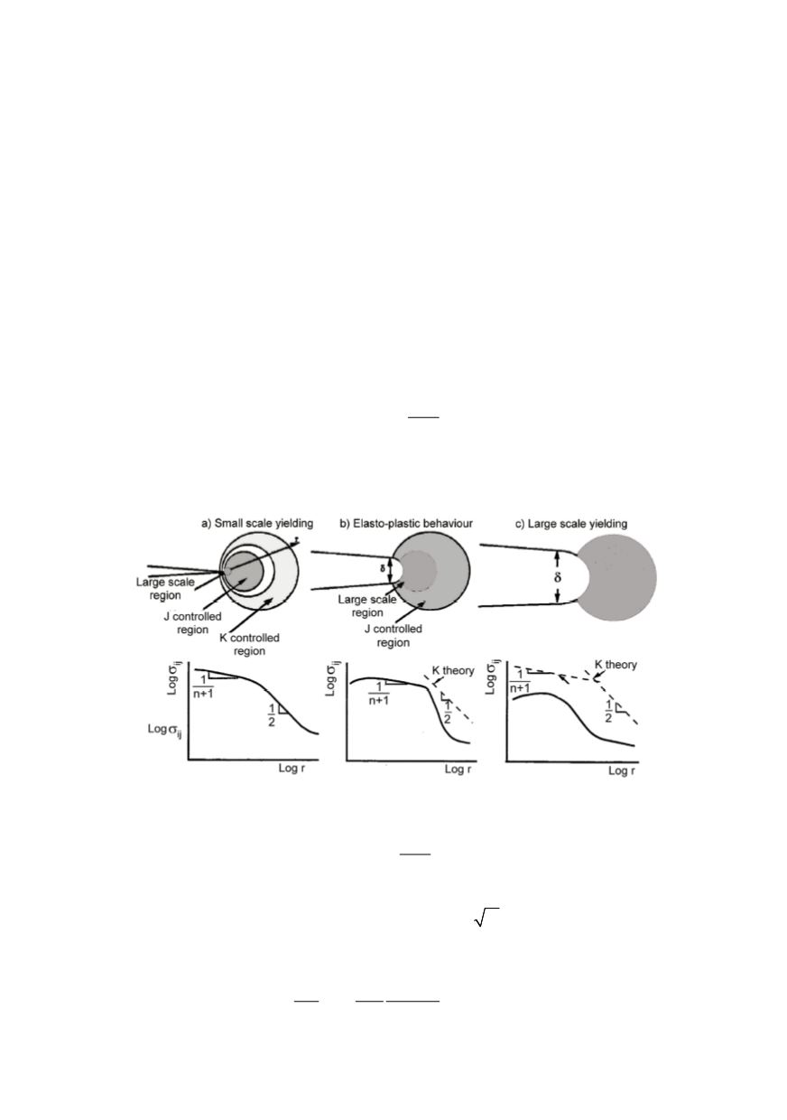
stress distribution around crack tip shown by broken line in Fig. 10 b).
In addition, region on the tip, not controlled by the solution is becoming much larger,
HRR solution is no more valid in this area due to the crack blunting. It is favourable that
the stresses in the large strain region are lower than predicted by the HRR singularity.
Under large scale yielding conditions, Fig. 10c, the calculations both with
K
and
J
are
no more valid. If the material is sufficiently ductile to experience this state before fractu-
re, than the stresses at the tip are significantly favourable, not only because of lower
values (than predicted by both
J
and
K
theory) but also because of a loss in triaxiality.
The sizes of the
J
and
K
controlled regions depend on the size and geometry of the
structure with the crack. Based on larger dimensions these regions in case of real
structures exist considerable longer, and because of this for the evaluation of material
characteristics the specimen must satisfy corresponding conditions for its validity to the
real structures be guaranteed. For example, for
K
Ic
evaluation different standards require
that the specimen dimensions fulfil the following requirement:
2
,
2.5
IC
YC
K
B b
σ
⎛
⎞
≥ ⎜
⎟
⎝
⎠
(20)
where
B
is the specimen thickness and
b
the size of the uncracked ligament. Comparison
with the plastic zone correction shows that these should be no more than 1/50 of
specimen characteristic dimensions.
Figure 10: Scheme of the effect of plastic deformation on the crack tip stress field
For
J
Ic
evaluation requirements concerning the specimen size are different:
25 ,
Y
J
B b
σ
≥
(21)
where
σ
Y
is the flow stress, defined as the average between the yield and tensile strengths.
For mild steels with
σ
Y
= 350 MPa,
K
Ic
= 250 MPa
m
and
E
= 210 GPa according
this requirement, specimen size for
K
Ic
evaluation should be
B, b >
1.28 m
For
J
Ic
evaluation, however sufficient sizes of the specimen are:
2
(1 )
25
25
0.02 m
Ic
Ic
Y
Y
J
K
b
b
E
ν
σ
σ
−
>
=
>