
25
•
Application of material and loading parameters that allow for nonlinear behaviour.
Simple correction of stress intensity factor based on so-called plastic zone at crack tip
has been proposed by Irwin. This idea was further developed from many authors. First
real elastic-plastic parameter, crack opening displacement, has been proposed by Wells in
1961, and the
J
-integral is proposed by Rice few years latter. Both parameters are in the
relationship; about this will be told more in the subsequent discussions.
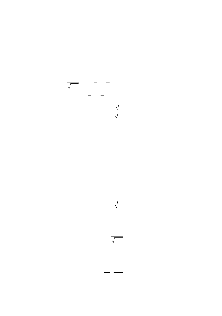
Based on the formula for the calculation of stresses at the crack tip
0
1 sin sin 3
2 2
cos
2 1 sin sin 3 + “negligible” terms of higher order
2 2
2
sin sin3
2 2
x
y
xy
K
r
θ
θ
θ
θ
σ
θ
θ
σ
π
τ
θ
θ
=
⎡
⎤
−⎢
⎥
⎡ ⎤
⎢
⎥
⎢ ⎥
⎢
⎥
=
+
⎢ ⎥
⎢
⎥
⎢ ⎥
⎢
⎥
⎢ ⎥ ⎣ ⎦
⎢
⎥
⎢
⎥
⎣
⎦
(7)
with
0
K
a
θ
σ π
=
=
(7a)
it is easy to establish that just at the tip
1 /
r
singularity exists and this relationship
predicts infinite stresses at the crack tip, which no one material is able to resist.
Accordingly, analysis based on
σ
= f(K, r)
with the aim to compare with the strength
properties of the material (to evaluate safety margin) does have no sense. Based on this, it
is decided that
K
is „better“ parameter and fracture mechanics is born.
This was possible, because the structural materials deform plastically above the yield
stress and this limits, through the stress redistribution and crack blunting, this kind of
development of the maximal stresses.
However, this feature of structural materials is not
considered by elastic analysis, which becomes inadequate. Even worse, stress redistri-
bution leads to stress increase on remain part ahead the crack tip and raised values of the
stress intensity factor, so that the solution goes to the unsafe side.
3.1. Limits of LEFM (crack tip plasticity)
To avoid described situation, Irwin takes the increase of the effective
K
I
in conside-
ration through the increase of crack size against its real values
eff
eff
K Y a
σ π
=
(8)
Effective crack length
a
eff
is obtained adding plastic zone size
r
y
to the actual length
a
eff
= a + r
y
(9)
The correction is calculated based on stress in the crack plane (
θ
=0):
2
I
yy
K
r
σ
π
=
(10)
For plane stress conditions (
σ
zz
=
0), material yields when
σ
yy
=
σ
YS
, (yield strength for
uniaxial tension). Part in which materials stress field does not harden is cut, as shown in
Fig. 7. After substitution in (10) it follows
2
1
2
eff
y
Ys
K
r
π σ
⎛
⎞
= ⎜
⎟
⎝
⎠
(11)
Similarly, the correction for plane strain condition will produce lower value:


