


 187 / 352

183
The geometric inter-relation between
w
and
t
is shown in Fig. 9.c. With reference to
these figures, it can be written that
OC = OB cos
α
=
t
cos
α
since OB =
t
, and
DB = AC = OC - OA =
t
cos
α
- w
since OA = w
Similarly,
DA = BC = OB sin
α
= t
sin
α
, and
DB cos
FD =
tg
tg
t
w
α
α
α
−
=
Here, F
denotes the point at which the stretch zone ends and ductile tearing starts, as
shown in Figure 9.b. Hence, FA is the SZD of height
h
,
and therefore
SZD =
h
= FA = FD + DA
cos
sin .tg
SZD
tg
t
t
w
h
α
α α
α
+
−
= =
a.
b.
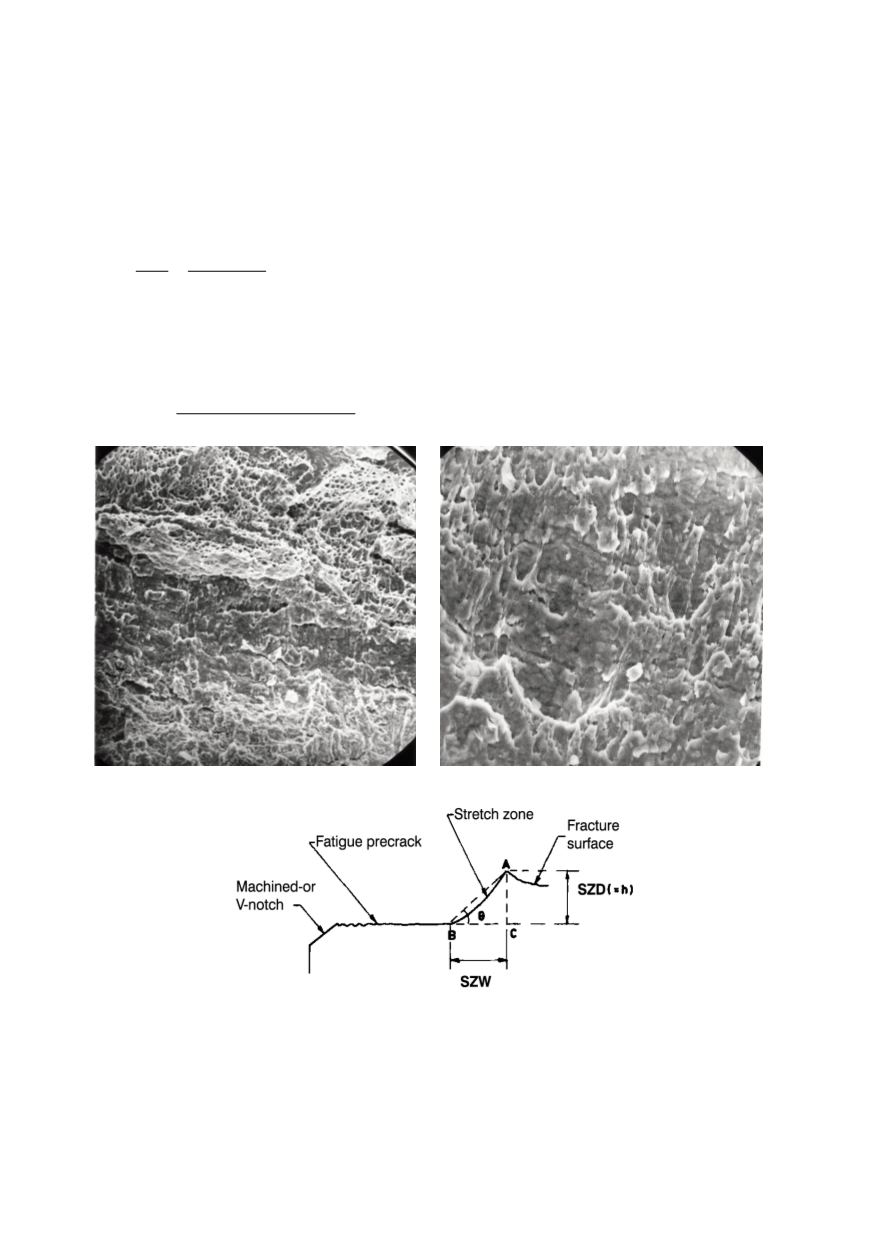
Figure 7. Scanning electron microscope (SEM) pictures of (a) fracture surface and (b) stretch zone
Figure 8: Schematic of the crack profile depicting the stretch zone components
SZW - stretch zone width, SZD - stretch zone depth
If the specimen is tilted through an angle of
α
= 45°, then
SZD =
h
=
2t - w
(3)