


 185 / 352

181
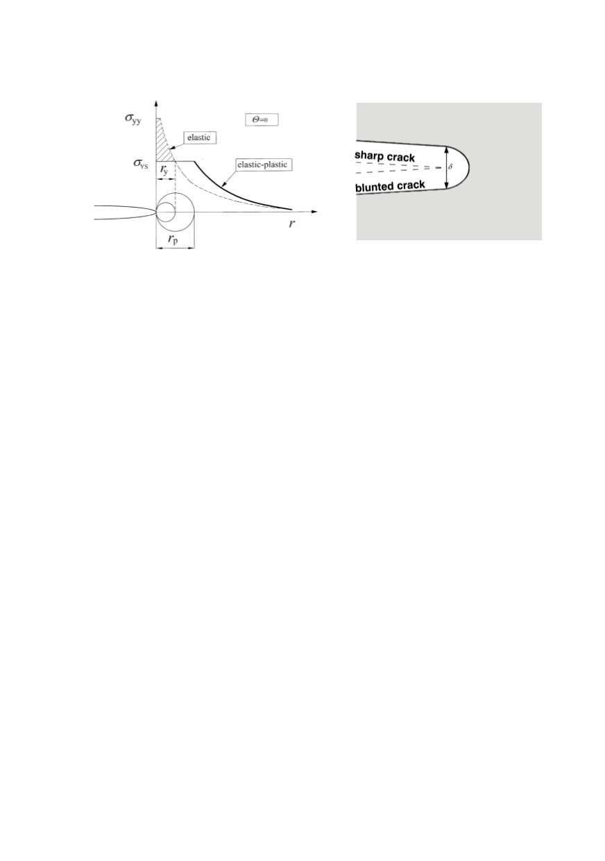
ning displacement (CTOD) can serve as a measure of fracture toughness, expressed in the
form of finite displacement
δ
at the crack tip.
Figure 3. First order and second order estimates of plastic
zone size (
r
y
and
r
p
, respectively) /4/
Figure 4. Initially sharp crack blunts
by plastic deformation, resulting in a
finite displacement (
δ
) at the crack tip
4. STRETCH ZONE
In linear-elastic fracture-toughness testing crack initiation is easy to detect because of
its brittle nature. In contrast, a crack in a ductile material will first blunt, extend virtually,
and then grow continuously in a stable manner, Fig. 5, exhibiting different stages of crack
extension in a ductile material. The effect of described behaviour on crack resistance cur-
ve (J-R curve) for ductile material is presented schematically in Fig. 6 by the change of J
integral with crack extension. The R curve is nearly vertical in the first phase of deforma-
tion and there is a small amount of apparent crack growth due to blunting. As J increases,
the material at the crack tip fails locally allowing the crack to advance further. Because
the R curve is rising, the initial crack growth is usually stable. Some experience is neces-
sary to determine the crack-initiation toughness in elastic plastic materials, as there is no
straightforward procedure for evaluating a single correct ductile fracture toughness value.
Before stable tearing, virtual crack extension in ductile materials leaves a signature of
the crack-initiation and blunting phenomena called the stretch zone. This featureless re-
gion lies between the fatigue precrack front and the onset of ductile tearing, Fig 7 /5/. The
formation, shape, and size of the stretch zone are characteristics of the material /6, 7/. In
highly ductile materials, the stretch zone would normally have two components: a
horizontal component called the stretch-zone width (SZW) and a vertical relief of the
crack front called the stretch-zone depth (SZD), as depicted in Fig. 8. Both the SZW and
SZD are closely related to the fracture toughness of a ductile material, and many attempts
have been made to measure the characteristic stretch-zone parameters on the fracture
surface of specimens and use them as an aid in determining the critical fracture tough-
ness. The measured SZW or SZD values can be used as convenient indicators for
identifying the crack initiation point on the experimentally generated crack-growth-resist-
ance (R) curve. There is no consensus among researchers whether ductile fracture tough-
ness should be estimated using SZW or SZD. Some of them use the SZW, while others
argue that SZD measurement is more appropriate than SZW for obtaining fracture tough-
ness of ductile materials /8/.
An advantage of SZW is that it can be measured directly on the specimen fractured
surface using a scanning electron microscope (SEM), whereas SZD measurements are