
175
that plastic deformations have been extended beyond crack on the distance
p
(Fig. 12. b)
and that plastic region can be presented as plastic strip, Barenblat-Dagdale’s model.
With these assumptions Dagdale’s model of plastic strip can be used. The solution of
this problem defined is given as a function of crack tip opening displacement,
δ
t
,
(
)
(
)
( )
0
t
X ,Y X ,
Z X
δ
δ
θ
=
+
(9)
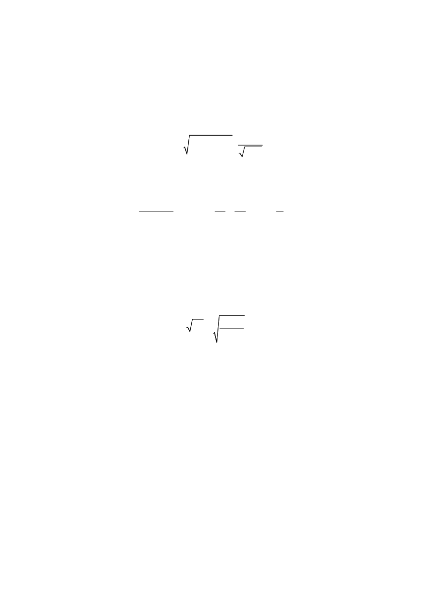
The main advantage of REI model is his simple usage since necessary data are given
in non-dimensional form for characteristic size of non-dimensional shell parameter λ:
(
)
2
4
2
12 1
a
R h
λ
ν
= ⋅ − ⋅
⋅
(10)
where
R
is shell radius, and
ν
Poason's coefficient. REI model can be applied to any axial
crack in cylindrical pressure vessel.
Equation for
J
integral with certain simplifications is:
0 2
2
1 2
0 5
4
*
eh
J E
d
J m
,
d d
h
a R
δ
θ
⎡
⎤
⋅
⎛
⎞
= =
+ ⋅
−
⎢
⎥
⎜
⎟
⋅ ⋅
⎝
⎠
⎣
⎦
(11)
For calculating shell parameter,
λ
, in this case the value
a
p
should be applied as crack
length in Eq. (10).
The parameters of plastic zone
α
=
a
/
a
p
=
λ
/
λ
p
, necessary for calculating, is taken
according to diagram (Fig. 13) where
a correlation between zone
α
and load
normalised
by applied pressure
p
is used
N
0
/(
hR
eh
) = (
pR
)/(
hR
eh
)
(12)
to obtain the values
2
4
*
eh
J E
J
aR
⋅
=
(13)
for different parameter sizes
λ
p
.
The values of
J*
integral are calculate for different ratios of crack depth
d
and vessel
wall thickness
h
,
d
/
h
(Fig. 12.b), and in Fig. 13 presented for typical parameter values
λ
p
(0; 1; 2; 3) /14, 15, 16/. Obtained diagrams are used for predicting fractures of cracked
cylindrical pressure vessel.
The effect of welding residual stresses and imperfections on the behaviour of crack in
pressure vessel is experimentally investigated /17, 18/, testing four plate samples, welded
of microalloyed
T.StE460 steel. Surface cracks tips were located in the HAZ of samples,
as presented in Fig.14. In order to analysed the effect of residual stresses, two plates were
post-weld heat treated (P1 and P2), and two were not (P3 and P4). The imperfections in
geometry were found in all four plates in such a way that plates P1 and P3 were distorted
up (the crack tip is directed to convex side), and plates P2 and P4 distorted down (the
crack tip to the concave side), for an angle of 1° in both cases, Fig.15. It was concluded
that the most favourable situation regarding fracture mechanics parameter is for plate P2
(post-weld heat treated, crack tip on concave side), whereas plate P3 presented the worst
case. Experimental results of
J
integral direct measurements from Ref. /18/ as relationship
J
integral vs. remote stress
σ
are compared here with the results obtained applying REI
model, as presented in Fig.16.


