


 177 / 352

173
For the loading by mass of vessel and the mass of working and test fluid, the greatest
displacements took place in front and back lids in the region of nozzles U, X, Z and P, Q,
and the values are within the allowed limits. Stresses in nozzles U, X locations are very
close to the material allowed stress, Fig. 11.
Surface elements exposed to compression or shear should satisfy stability conditions.
Stability of shell element is checked on the mantle surface between the lugs for
dimensions: wall thickness
h
= 10 mm, section length
a
= 4300 mm, section width
b
=
335 mm.
Critical normal,
σ
cr
, and shear stresses,
τ
cr
, are obtained using the expressions:
2
kr
s
K E
b
σ
σ
⎛ ⎞
= ⋅ ⋅ ⎜ ⎟
⎝ ⎠
2
kr
s
K E
b
τ
τ
⎛ ⎞
= ⋅ ⋅ ⎜ ⎟
⎝ ⎠
(8)
For the ratio
b
/
a
= 335/4300 = 0.078 contour condition coefficients for fixed edges of
mantle elements are
K
σ
= 3.8 and
K
τ
= 8, so critical stresses are:
2
1 0
3 8 210000
711 1
33 5
kr
.
.
. MPa
.
σ
⎛
⎞
= ⋅
⋅
= ⋅
⎜
⎟
⎝
⎠
2
1 0
8 210000
1497 0
33 5
kr
.
. MPa
.
τ
⎛
⎞
= ⋅
⋅
=
⋅
⎜
⎟
⎝
⎠
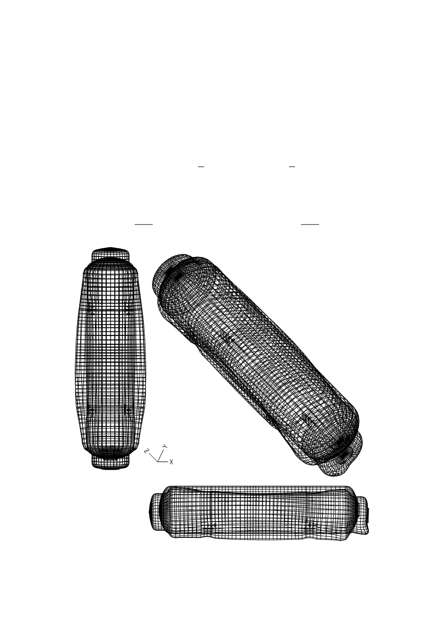
Figure 10: Displacements of the nodes or the one of the loading cases