


 176 / 352

172
Dead weight of vessel (4400 kg) is used at elevation of empty tank by shrouds under
the angle of 45
°
, item 10.
Allowable deformations and stresses
The highest allowable deformation is defined by the request that applied loadings must
not produce permanent deformation, according to selected material of the vessel, fine
grained structural steel TStE355, Table 1.
Table 1: Mechanical characteristics of TStE355 steel
Young modulus Yield strength Tensile strength
Elongation
Impact toughness, J, at
E
, MPa
R
eH
, MPa
R
m
, MPa
L
o
= 5
d
, %
-20
°
C
-50
°
C
200000
414 - 436
574 - 582
28-30
176-200
50-53
For adopted safety factor
S
= 1.1 allowable stress
σ
al
and elongation
l
al
are:
σ
al
=
R
eH
/
S
= 414 / 1.1 = 376 MPa
l
al
=
σ
al
x L/
E
=376X835.7/ 200000 = 15.7 mm
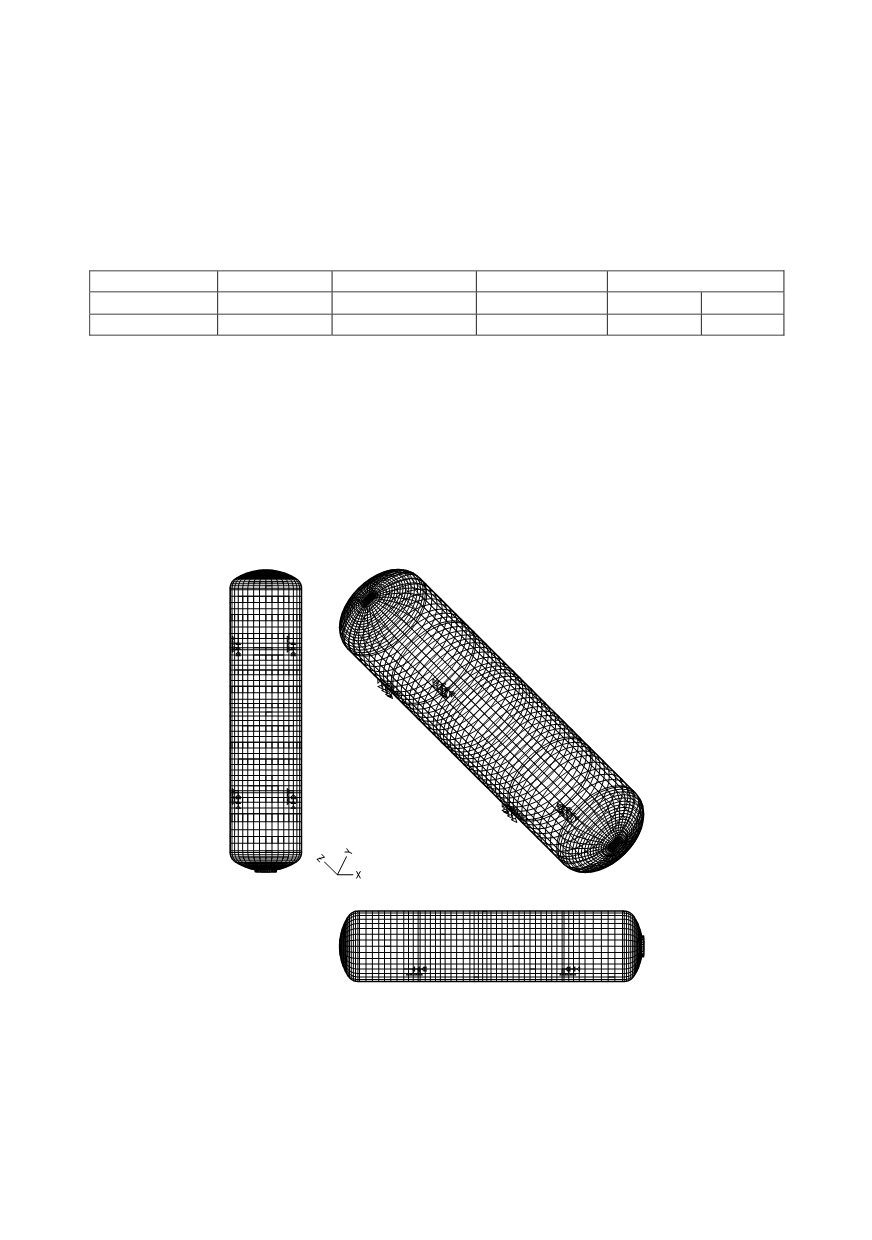
Model of tank structure
Strength calculation is made by finite element method (FEM) in KOMIPS program.
In static calculation tank is considered as a space structure of connected plates
elements (quadratic and triangular) with variable cross section. The whole bearing struc-
ture is reduced to middle plane of shell and front and rear lids. All the connections are
reduced to one of considered planes. Accepted model, Fig. 9, consisted of 3242 nodes and
3308 plate elements /13/. This calculation is used to derive requested conclusions.
Figure 9: Accepted finite elements model of tank used for calculation
For plate elements, maximum equivalent stresses and strains in considered section
have been calculated using suitable software modules. Displacements of the nodes for
typical and critical loadings by mass of vessel and the mass of working and test fluid are
shown in Fig. 10, with stresses calculated from strains.