


 16 / 352

12
Unfortunately, no chemical analysis for flange plate material was available. Micro-
graphs show that the steel contains a highly banded, ferritic-pearlitic microstructure of a
somewhat finer grain size than that of the bracing material (see Table 1). On the other
hand, the MnS-inclusion content is not only higher than for the bracing material, but is
present in the undesirable shape of long, rolled out laths. This, of course, gives the mate-
rial its very poor transverse ductility (1-7%). It is therefore hardly surprising that sig-
nificant lamellar tearing was observed in connection with both the fillet and butt welds.
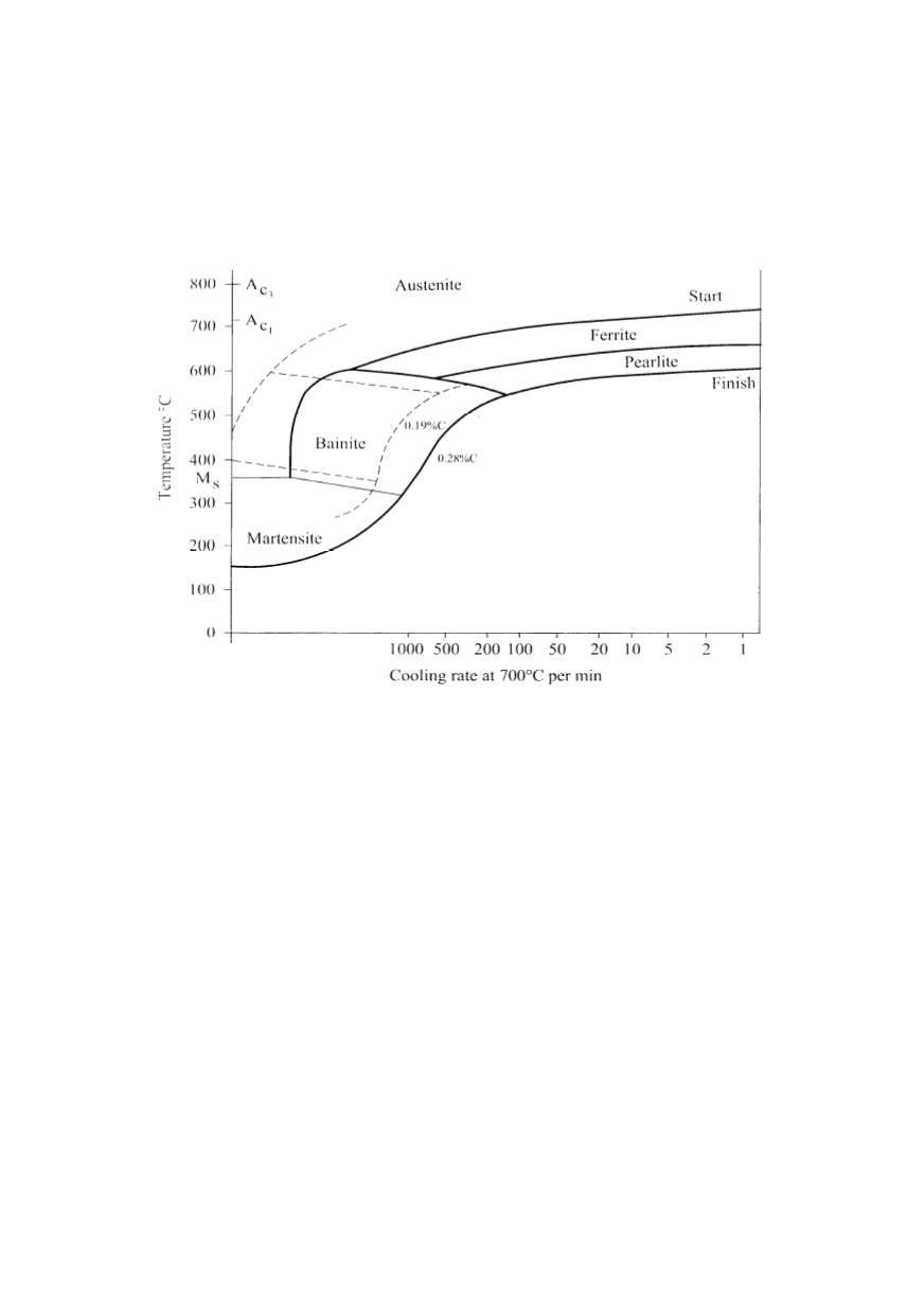
Figure 8: Continuous cooling diagram for microalloyed steel containing 0.19%C
The root cracks and toe cracks reported for the butt weld are presumably due to cold
(hydrogen) cracking. Assuming the use of the same basic electrodes as specified for the
fillet weld, cold cracking problems should not normally occur, although it is not known
whether the electrodes were properly dried prior to use. Another possible contributory
cause to these cracks may be in the form of liquation cracking, this often arising if
elongated MnS particles intersect the fusion zone, as seems likely in the case of the butt
weld. In any case, the hardness measurements in the HAZ of this material (Fig. 7) are
somewhat higher than for the bracing material HAZ. This suggests the presence of a
significant amount of the bainitic-martensitic structure, susceptible to cold cracking.
2.5. Mechanism of failure: main conclusions
There appears to be a number of factors which could possibly have contributed to the
failure of the D-6 bracing, with the resulting capsize of the Alexander Kielland platform.
Of these the following are probably the most important:
1. The considerable amounts of lamellar tearing in the flange plate and the extensive root
crack in the butt weld both contribute to the weakening of the sonar flange-plate in its
capacity as structural strengthener. This, together with the resulting increased stress
concentration at the hole, evidently induced cracking (or caused existing cracks to grow)
around the periphery of the flange plate in the fillet weld.
2. The poor profile of the fillet weld contributed to reduced fatigue strength of the weld.