


 14 / 352

10
2.4. Analysis of weld thermal cycle effects on the bracing and flange plate materials
The material of main bracing was Nb -microalloyed, fine grained, high strength steel,
Table 1. In normalized conditions the steel contains a fine dispersion of NbC precipitate
which stabilizes and refines the grain size. The carbon content is high (0.17%), giving the
steel its fairly high C
equiv
value (0.41). Aluminium (0.044 wt %) is mainly present as a
deoxidizer, there evidently being little or no nitrogen present to form AlN or Nb(CN).
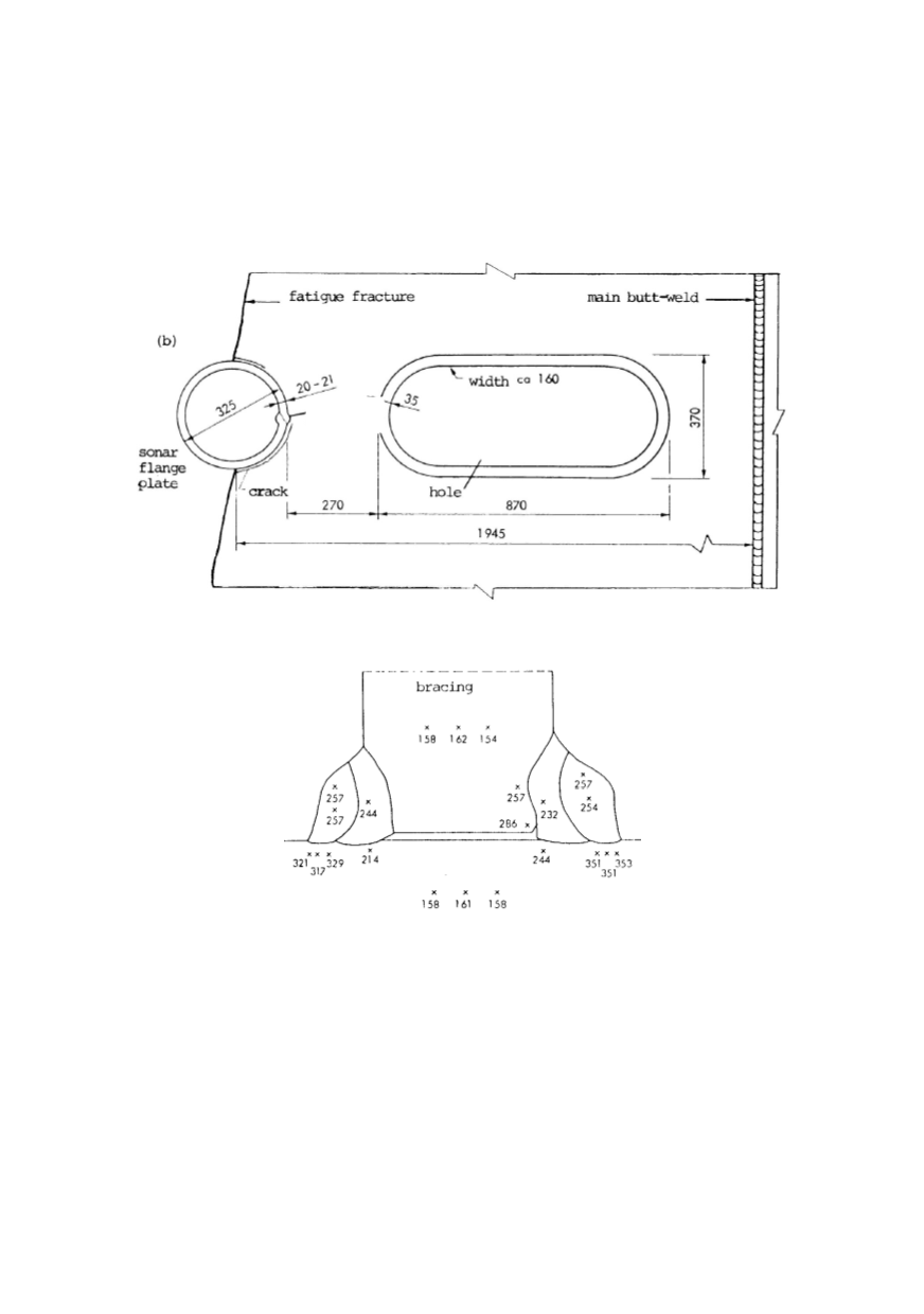
Figure 6: Crack initiating in a fillet weld of sonar flange plate and ending in cracked butt weld.
The position of final fatigue fracture is indicated
Figure 7: Hardness distribution in failed fillet welded joint between bracing and flange plate
The continuous cooling diagram for the steel is similar
to
that shown in Fig. 8 (for the
0.19% C content), in which it is seen that the relatively high cooling rates of MMA
welding are likely to give a mainly bainitic microstructure. The presence of Nb, if it is in
solution in the austenite, further tends to promote the lower bainite transformation. In
other words, this alloy is a typical example of today's sophisticated steels which aim to
possess the ideal combination of high strength and acceptable weldability.
The solubility temperature of NbC in steel is given by equation
[
][ ]
10
1og %Nb %C 2.96 7510 /
T
= −
(1)
and thus it is estimated to be
T
~ 1150
°
C. During a rapid thermal cycle, as in welding, the
carbide is effectively superheated. On this basis, knowing the welding energy
Q
used
Butt-weld
(Cracked)