


 127 / 352

123
mat
Y mat
mat
2
2
1
1
J E
E
K
σ
δ
ν
ν
⋅
⋅
⋅
=
=
−
−
(23)
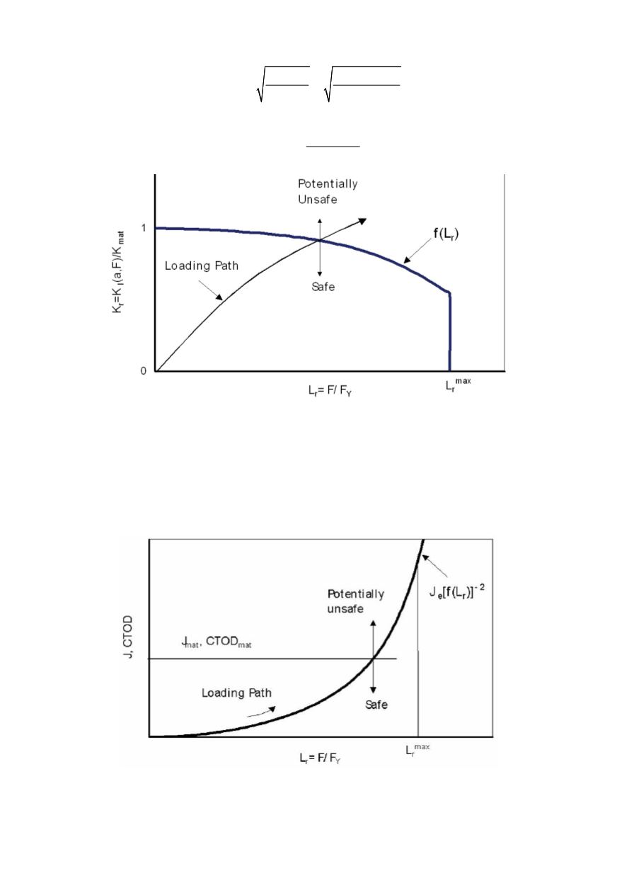
Failure criteria:
(
)
I
mat
r
K a, F
f ( L )
K
<
(24)
Figure 19: Failure assessment diagram based on a FAD philosophy
In contrast to this in the crack driving force (CDF) route the crack tip loading in the
component is determined in a separate step. It is then compared with the fracture resis-
tance of the material. If the crack tip loading is less than the fracture resistance the
component is safe, otherwise it is potentially unsafe. The basic relations are given by Eqs.
(25) and (26), and in next text for limit toughness and failure criteria.
Figure 20: Failure assessment based on a CDF philosophy