
129
Requirements in this respect are realised by the modification of standard isoparametric
elements in adequate way. Elastic singular behaviour
1 /
r
is presented by the isopara-
metric finite elements (with 8 nodes in 2D and 20 nodes by 3D) if the mean node at
element side is moved in direction of crack tip at quarter position. Additionally, to
consider the plasticity, two corner nodes and mean nodes at crack tip must have identical
position from the beginning (the corresponding element edge collaborates in point, in
which way the element passes from rectangular in triangle – from there the name), but
under loading influence they may, to realistically represent crack blunting, be separated.
Because that these collaborate rectangular elements include
1 /
r
and
r
–1
terms, it is
assumed that they will sufficiently accurate describe the behaviour at crack tip in
combination with the standard description of material law in exponential form.
Accordingly, there are three different kinds of elements for crack tip modelling:
•
Deformed „quarter-point“ element: by this element elastic singularity
1 /
r
is
accurately described.
•
Collaborated element (from rectangular to triangle) that posses 3 different nodes at
crack tip. With this element
r
-1
singularity is realised, which corresponds to elastic-
ideal plastic materials.
•
Element that combines both above changes and in this way includes
1 /
r
and
r
-1
singular terms.
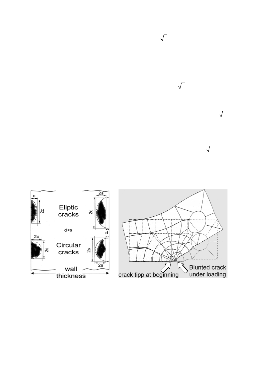
If such elements are used for crack modelling, then a couple of their nodes at crack tip
share the same position. When the model is loaded the elements at tip are deformed and
these nodes starts to separate. This leads to crack blunting and realistic modelling of crack
tip behaviour, as shown in Fig. 4.
Figure 3: Idealization of surface and
embedded cracks
Figure 4: Crack tip simulation with the finite element
method
Using finite element method the evaluation of stress intensity and
J
-integral values for
3D-geometries of structures and cracks becomes possible. Independence on integration
contour is principally only valid for 2D case. By 3D-geometry, as in the case of surface
crack (Fig. 5) the independence is only approximative and the deviation is more
expressed with the growing distance from crack tip.


