


 121 / 352

117
In the case of linear-elastic deformation behaviour, the crack tip loading can be
determined by superposition the K factor due to primary and the K factor due to
secondary stress:
I
I
p
s
r
mat
K K
K
K
ρ
+
=
+
(1)
and in the CDF route as,
2
I
I
1
p
s
'
r
K K
J
f ( L )
E
ρ
⎡
⎤ +
= × ⎢
⎥
−
⎢
⎥
⎣
⎦
(2)
2
I
I
1
p
s
Y
r
K K
E'
f ( L )
δ
σ
ρ
⎡
⎤ +
=
× ⎢
⎥
⋅
−
⎢
⎥
⎣
⎦
(3)
The quantity
ρ
characterizes the difference between the actual crack tip loading and
the crack tip loading which would result from simple superposition of
K
I
p
and
K
I
s
. Using
p
ref
r
Y
L
σ
σ
=
(4)
it is dependent on the ligament of plasticity,
L
r
(which is a function on primary loading,
on the magnitude of the secondary stress, and on the equation applied for
f
(
L
r
).
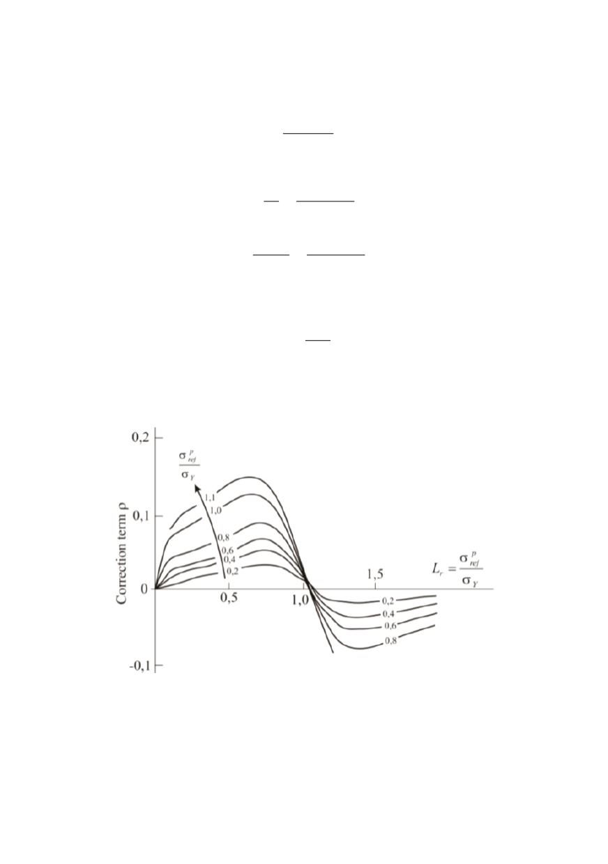
Therefore, the correction term
ρ
can be determined from the plot given in the Fig. 13.
Figure 13: Correction term
ρ
in function of
L
r
6.3. Crack type and orientation
Real flaw shapes are idealized by substitute geometries such as rectangles, ellipses and
semi-ellipses (Figs. 14 and 15). The idealization has to been done such that the crack tip
loading will be overestimated.