


 120 / 352

116
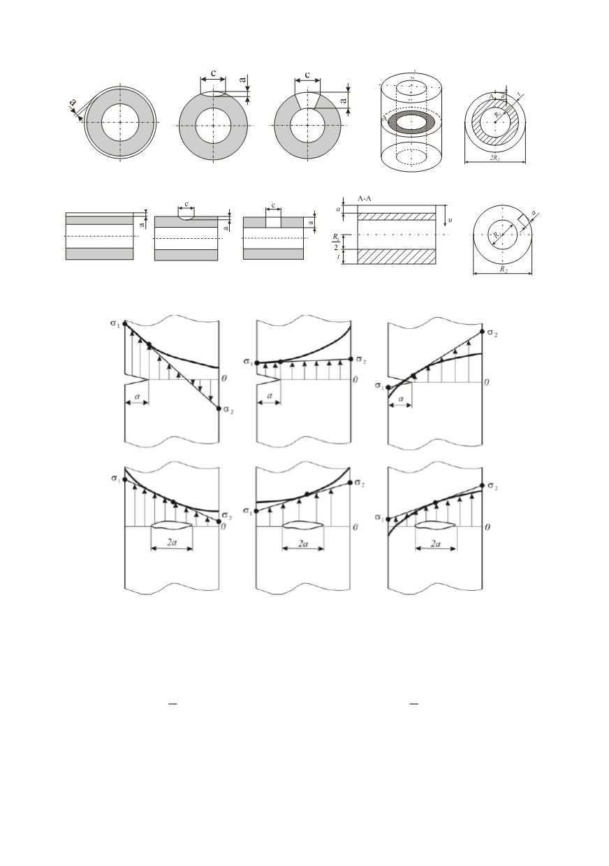
a) Radial crack in disk
b) Disk cracked longitudinally
Figure 11: Radial (a) and longitudinal (b) cracks in a disk
Figure 12: Stress profile through the thickness determined by finite element analysis /12/
Membrane and bending stress components are calculated from the principal stresses
normal stresses,
σ
1
and
σ
2
:
Membrane stress component
Bending stress component
(
)
1 2
1
2
m
σ
σ
σ
= +
(
)
1 2
1
2
b
σ
σ
σ
= −
If the cross section contains a crack, the secondary stresses can be a major loading
component (typical secondary stresses are welding residual stresses). Secondary stresses
are taken into account in determining the K factor, but not in determining the limit load,
FY, or the degree of ligament plasticity, Lr.