


 81 / 352

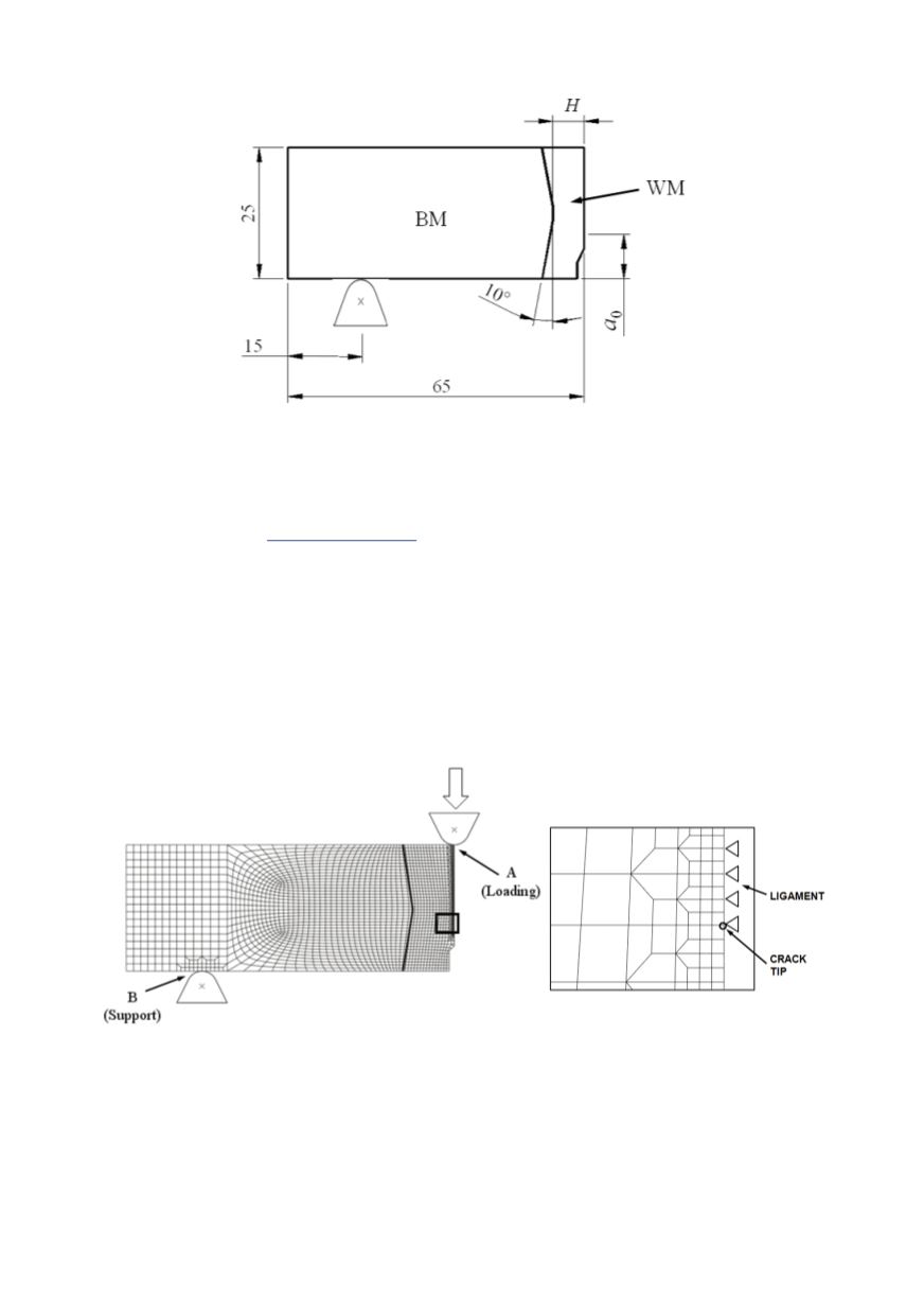
77
Figure 5: Dimensions of the SENB specimen and weld metal (2
H
= 6, 12 and 18 mm)
The specimen is analysed under plane strain conditions, and the finite element (FE)
mesh is shown in Fig. 6, with magnification of the region near the crack tip. Crack tip is
modelled using a refined FE mesh without singular elements. Finite element software
package ABAQUS (
www.simulia.com )is used for numerical analysis, and the CGM is
applied through user material subroutine created by Zhang, based on /21/. The initial void
volume fraction
f
0
is set as equal to
f
v
, according to /25, 36/. FE calculations are carried
out with the values of Tvergaard constitutive parameters
q
1
= 1.5 and
q
2
= 1. External
loading is defined by prescribing displacement of the rigid body, which is in contact with
the model (position A, Fig. 6). Contact is also used for defining the boundary conditions
for support (position B). It is important to note that the heat affected zone (HAZ) is not
taken into account, based on /37, 38/, since the crack is located in the weld metal, along
the axis of symmetry of the joint. Coupled approach to ductile fracture (the GTN model)
was also used in /17, 18/ for assessment of ductile fracture initiation in these joints.
Figure 6: FE mesh of one half of SENB specimen (left) and detail around the crack tip (right)
5.3. Crack growth initiation
Distribution of void volume fraction
f
near the crack tip at the crack growth initiation
is shown in Fig. 7 for the joint 6 mm wide and 20-node elements with reduced integration
and size 0.15x0.15 mm. Concentration of large values very close to the crack tip is
obvious. One can also see a large variation of
f
in the elements near the crack tip.