


 80 / 352

76
E1245-89 standard and /34/), by quantitative microstructural analysis using optical
microscope, based on the equality with surface fraction of detected inclusions
A
A
/34/:
i
v
A
T
A
f = A =
A
(19)
where
A
i
is the area of inclusions and
A
T
is the measurement field area.
For determining the mean free path between non-metallic inclusions
λ
according to
ASTM E1245-89 standard, in each measurement field five horizontal measuring lines are
drawn, and the number of interceptions of inclusions per measurement line unit,
N
L
, is
determined. The mean free path is mean edge-to-edge distance between inclusions:
1
A
L
A
N
λ
−
=
(20)
The final value of
λ
is determined, in the same way as the volume fraction of non-
metallic inclusions
f
v
, as the mean value for all measurement fields.
The values of
f
v
and
λ
for both materials are given in Table 3.
0.0
0.2
0.4
0.6
0.8
1.0
0
200
400
600
800
1000
1200
1400
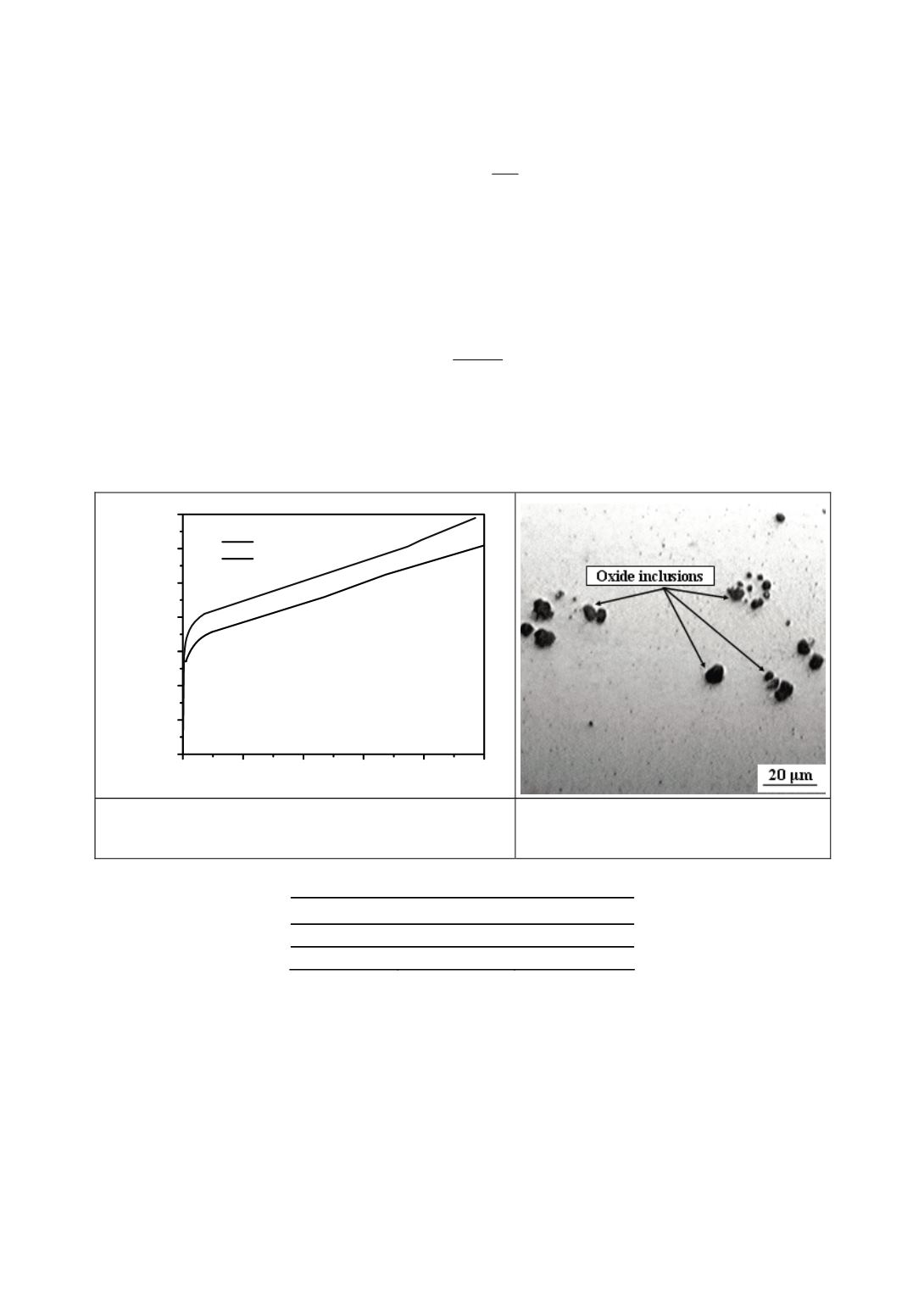
WM:
E
= 183.8 GPa
R
P
0.2
= 648 MPa
R
m
= 744 MPa
BM
OM
ε
BM:
E
= 202.9 GPa
R
P
0.2
= 545 MPa
R
m
= 648 MPa
σ
[MPa]
Figure 3. Tensile properties and true stress - true strain
curves of BM and WM at room temperature
Figure 4. Microphotograph of oxides in
base metal
Table 3: Volume fraction
f
v
and mean free path between non-metallic inclusions
λ
Material
f
v
λ [µm]
BM
0.012164
103.1336
WM
0.006342
157.4719
5.2. Finite element model
Single-edge notched bend (SENB) specimens are used for examination of the welded
joints, with different width of WM (and joint) 2
H
: 6, 12 and 18 mm, Fig. 5. Crack tip
opening displacement (CTOD) values are determined, both experimentally and by
numerical calculations, using
δ
5
concept /35/.