


 41 / 352

37
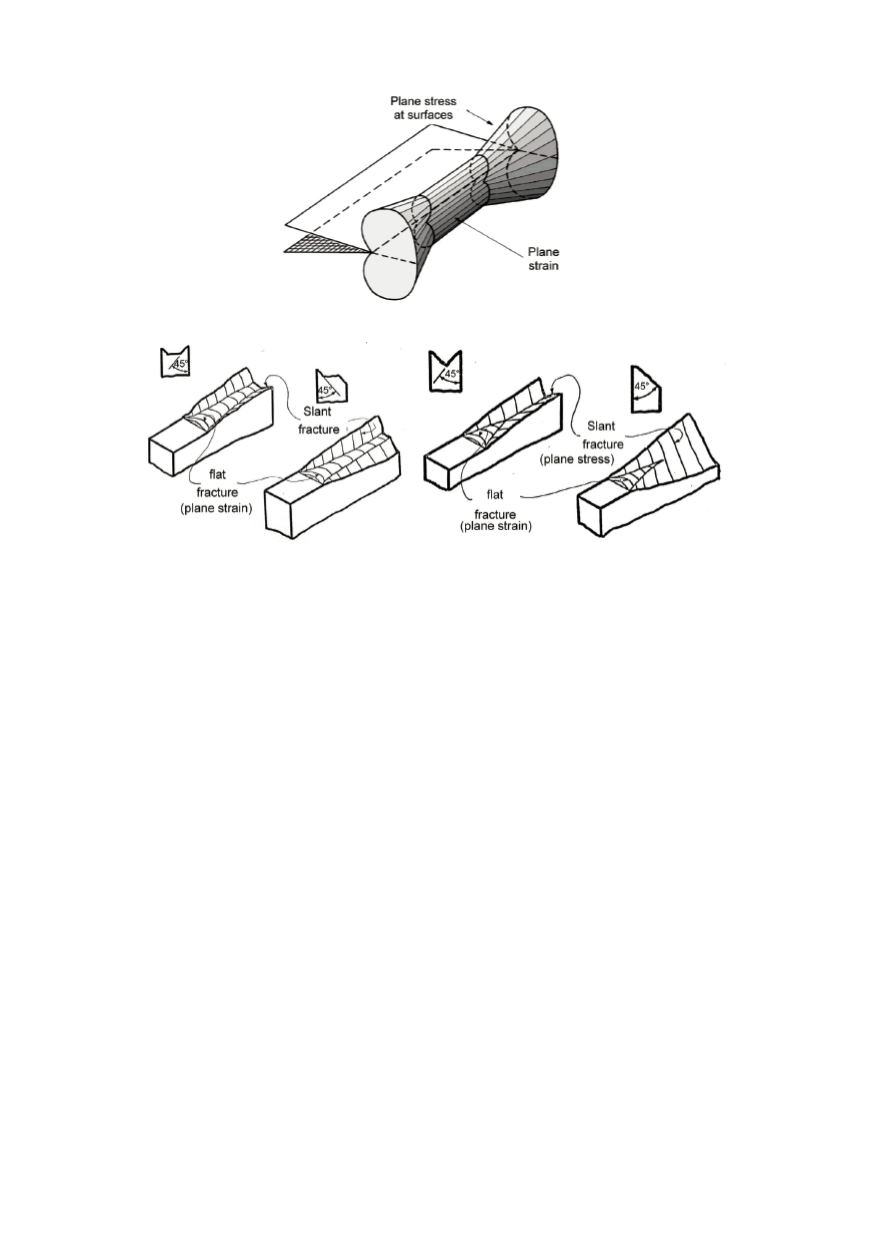
Figure 20: Through thickness plastic zone in a plate
Figure 21: Typical forms of the fracture surface for plate or thin wall structure
The crack surface is observed to rotate in this region so as to make an angle of
approximately 45° with load direction. These inclined portions of the crack surface near
the plate surfaces are known as "shear lips". The proportions of each type of crack surface
depend on material properties (yield strength, strain hardening exponent), specimen
geometry (crack length, plate thickness) and loading. The proportion of the fracture
surface associated with slant fracture or shear lips increases with decreasing plate
thickness and in very thin plates in which the shear lips merge into each other the fracture
surface completely rotate to 45°. The initial straight fracture line decreases with increase
in load level, showing the dependence of the behaviour on load level.
The postulates that "plane strain condition" are in all cases on the safe side cannot be
fully accepted, as it refers only to "out-of-plane" constraint which are normal to the crack
growth direction, and does not allow for explaining the effects of varying "in-plane"
constraint in the direction of crack growth. Anyway, specimens for fracture toughness
measurement the corresponding requirements in both directions must be fulfilled.
Although, the constraint problem is connected to the stress state in space and to the
effect of hydrostatic stresses, the first attempts to take this phenomenon into account were
based on the solutions for
K
and
J
. As known the solution based on
K
is realised by
neglecting higher terms in the solution, and the solution for
J
with the assumption for
non-linear elastic material. Based on this, the parameters
T
-stress and
Q
-factor has been
involved to consider the neglected parts of the solution and so ignored effects of
geometry and load level. Application of these parameters have demonstrated that scatter
of experimental data can be significantly reduced by correcting for constraint effects.
The two-parameter formulation based on the
T
-stress approach is defined through the
expansion of the linear elastic stress field about the crack tip using the form