


 46 / 352

42
For this method (Option 2)
K
r
= f(L
r
)
is defined with the following formula
3
2
ref
r Y
r
r Y
ref
E
L
K
L
E
ε
σ
σ
ε
⎡
⎤
=
+ ⎢
⎥
⎢
⎥
⎣
⎦
(39)
FAD in R-6 is cut at someone level of
L
r
that depends on material properties
.
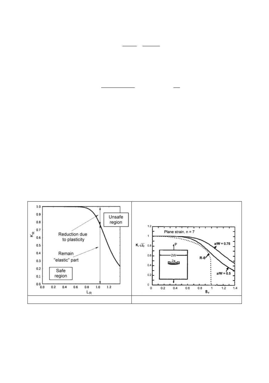
Elastic-plastic crack driving force evaluated based on the EPRI procedure can also be
presented in FAD form. For this purpose, first are defined the ratios
( )
( )
e
r
e eff
pl
J a
J
J a J
=
+
and
r
o
P S
P
=
(40)
The equivalent
K
r
is equal to the square root of
J
r
.
Results are compared in Fig. 26.
In the FAD both possible effects based on comparison of crack driving force with the
parameters of material toughness and plastic collapse are considered in the same time.
Complete R-6 procedure contains different levels, each of increasing complexity,
assuming to be less conservative than that of lower level, applied in dependence of the
results and significance of the case. However analyses based on resistance curve (Fig. 15)
may give more accurate results and demonstrate the sensitivity of the problem.
Structural integrity assessment always includes the safety factor. Evaluation of the
reliability level is complex, especially in fracture mechanics that includes more
parameters. Starting from the base definition that safety factor is the ratio of load leading
to failure and expected load of the structure, the safety factor in the FAD is accepted as
the ratio of segments
OB/OA
(Fig. 27). But, safety factor based on crack must consider
that the stress values are dependent on square root of crack size. For that so accepted
safety factor must be proved in detail.
Figure 25. Failure assessment diagram-FAD
Figure 26. Comparison of FAD for EPRI and R-6