


 10 / 352

6
2.1. The construction and fitting of the sonar flange plate
As shown in Fig. 3.b, the flange plate is essentially a short, circular, hollow cylinder,
325 mm in diameter, wall thickness 20 mm and 228 mm long. Similar flange plates were
fitted to three of the main braces, i.e. B-5, D-6 and A-5. The flange plate material was
fine-grained pearlitic-ferritic steel, shaped by bending and butt welding. The profile of the
butt weld was of an X form, welded from both inside and outside employing 2 runs on the
inside and up to four on the outside. The welding procedure applied was Manual Metal
Arc (MMA), using flux-covered electrodes.
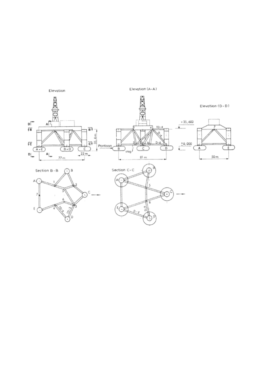
Figure 2: General design view of a pentagon type platform
The sonar flange plate was located at a flame-cut hole in the bracing, of approximately
3-5 mm larger diameter than the flange itself. The flange plate was then welded in
position using MMA welding of 2-3 runs per weld, employing fillet welds both inside
and outside the main brace plate, Fig. 3.b. Flux-covered basic electrodes, 5 mm in
diameter, were selected. The weld’s
dimension ‘
a’
was 6 mm, but the number of runs per
weld was not specified. Preheat was neither specified nor employed.
2.2. Capsize of the Alexander Kielland
On the 27
th
March, 1980, the day of the disaster, the weather in the North Sea was
stormy with mist and rain and visibility down to about a kilometre. It was cold, with an
air temperature of 4-6
°
C and a sea temperature of 6
°
C. As the day progressed the weather
deteriorated, with the wind blowing at 20 m/s, churning up waves of 6-8 m in height.
About half an hour later, at 6.28 p.m., the radio officer on board the Kielland heard a loud
thump from below. Not too much notice was paid to begin with, since such noises are not
unusual in heavy seas. Soon after the first thump, however, came another and this was
followed by a definite listing of the platform. Minutes after the second thump was heard,