


 137 / 352

133
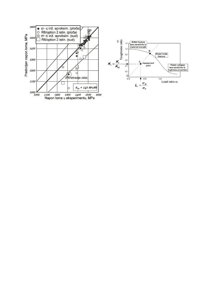
Figure 8: Comparison of test results for the
validation of
σ−ε
-
method
Figure 9: Different areas for FAD influence
parameters
4. METHODS AND PROCEDURES
Limitation with which is confronted the user by application of fracture mechanics are
not only based on theoretical solutions. Often the largest problems appear by the prepa-
ration of data necessary for calculation, as for example is the real crack size, whose
measurement based on limited sensitivity of equipment very soon became uncertain. This
means that the defects below some size cannot be detected reliably, and for that they must
be tolerated. It is the question, what to do if the existence of those defects is evident,
although they can not be detected? The answer to this question is found in method that at
the beginning had simply named “crack tolerance”, but with the time is developed in a
complex method, like “fitness-for-purpose” (FFP) or “retirement-for-cause”, included in
modern codes. In codes as API 579, BS 7910 and R6 description in detail of application
procedures are given, requiring calculations by complex models based on finite elements.
This kind of approach allow the optimisation of equipment management based on
planed inspections, maintenance, repairs, life extension, stop the operation and eventual
component retirement before its fracture can cause failure of equipment and unplanned
long-term and expensive outage of service. This approach enables to extend the life of
equipment, far above nominal calculated life of components.
Defects that appear in structural components are of different kind, each with its own
distribution regarding the size and number (Fig. 10):
•
Defect that are the result of the material production process, as porosity, micro-cracks,
inclusions and surface pits. This kind of discontinuities is usually below the typical
NDT detection capability, and requires design fully tolerating them.
•
Defects that are introduced during fabrication: machining marks, scratches or any type
of damage that could produce a crack like discontinuity. They are often large enough to
be detected by standard NDT and repaired.
•
Discontinuities that are formed in service
.
They include cracks formed by fatigue,
corrosion, creep and impact damage. Their origin can be any of the previously cited
defects. These discontinuities must be under the full control of damage tolerance
requirements and this means that they must be discovered in time and tracked during