
315
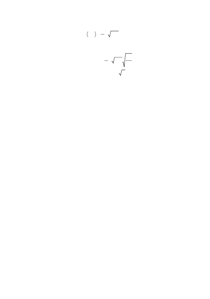
Let us look at the cohesion modulus of the discrete cohesive crack. From (13) it is
1/2
0
2
( , )
d
coh
S
K K S a I X R
π
π
= =
(20)
When the size of the cohesion zone is small compared to the crack length, the integral
in the Eq. (20) reduces to 2
R
/
a
0
, and simplified expression for the cohesion modulus is
i
0
0
2
2
d
coh R X
R
K
S a
a
π
π
⎡
⎤
=
⎣
⎦
(21)
This relation shows explicitly that the product
i
S R
determines material resistance to
crack propagation. The problem faced by the material engineers consists in finding a right
proportion between
S
and
R
; there exists a conflicting trend between the magnitude of the
cohesive strength (approximated by the inherent strength of the material) and length of
the cohesive zone. Increasing
S
, by increasing strength without paying attention to cohe-
sion toughness parameter, which describes the degree of ductility, lowers the length
R
and
thus it may
lead to
undesirable effects of increased brittleness. This is where the theore-
tical considerations involving the fracture quantum and the resulting discrete nature of
fracture at nano levels may prove to be useful in designing new materials. The formula
(21) shows that indeed there is an additional length involved in defining the cohesion
modulus. This is the length
a
0
. As seen from (21) in addition to the inherent strength
S
there are two other factors that influence material toughness; these are the fracture quan-
tum and the ratio of cohesive zone size to fracture quantum. This provides a material
engineer with additional degrees of freedom to work with.
Yet another variable affecting the cohesion modulus and material toughness that
should be considered is the roughness of the surface created in the fracture process.
4. DISCRETE COHESIVE MODEL FOR FRACTAL CRACKS
In this section two features typical of any fracture process are incorporate:
1. Roughness of the newly created surface due to varying degree of fractality (as
opposed to the assumption of perfectly smooth surface employed in the classical LEFM).
2. Discrete nature of the separation of two adjacent surfaces caused by decohesion (as
opposed to continuous character of the propagation process commonly assumed in all
local fracture criteria).
A fractal crack completed with the cohesive zone is considered. Therefore, all equa-
tions derived in the previous sections are used now and modify to fit the fractal model of
Wnuk and Yavari /13/. That is the only model available at the present time, although it is
only an approximation. The fractal crack model employed here is based on a simplifying
assumption, in which the original problem is approximated by considerations of a smooth
crack embedded in the stress field generated by a fractal crack, Wnuk and Yavari /27/.
The cohesive model implies existence of two stress intensity factors, one associated
with the applied stress,
K
σ
f
, and the other
K
S
f
assigned to the cohesive stress. Superscript
“
f
” emphasizes the fact that now fractal cracks are in question. When the discrete model
is employed these two entities should be replaced by their averages taken over the inter-
val (
c
,
c + a
0
), where
c
denotes the half-length of the crack and
a
0
is the fracture quantum.
For each value of the applied load one can determine the corresponding equilibrium
length of the cohesive zone. The calculation is using the finiteness condition


