


 105 / 352

101
low-strain hardening materials (
σ
UTS
/
σ
YS
∝
1.3), where
σ
UTS
is the ultimate tensile
strength, and ASTM E 647 recommends the use of the monotonic yield strength. For
higher-strain hardening materials, Eq. (6) and (7) may be too restrictive, and the criteria
may be relaxed by replacing the yield strength,
σ
YS
, with the effective yield strength,
σ
F
:
(
)
2
YS UTS
F
σ
σ
σ
+
=
(8)
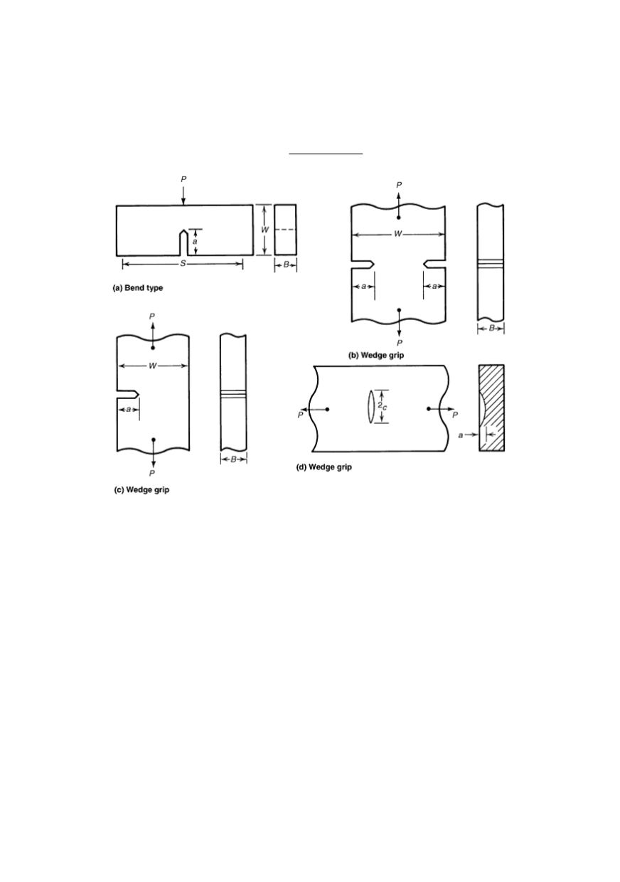
Figure 16: Alternative geometries of crack growth test specimens: a) Single-edge-crack bending.
b) Double-edge crack tension. c) Single-edge-crack tension. d) Surface-crack tension.
Fatigue crack growth rates are relatively insensitive to stress state (i.e. plane-stress or
plane-strain), there are some practical limitations on specimen thickness. ASTM E 647
recommends C(T) specimen thickness (
B
) range between 5 and 25% of width (
W
/20
≤
B
≥
W
/4), and M(T) specimens may have thicknesses up to 12% of width (
W
/8). For center-
cracked tension specimens, thickness should not exceed 25% of width. Similar ranges for
the thicknesses should be employed for other specimen types.
Although specimen thickness can vary, the amount of crack curvature in the specimen
will increase as the thickness increases. Because stress-intensity solutions are based on a
straight through-crack, a significant amount of curvature, if not properly accounted for,
can lead to an error in the data. Crack-curvature correction calculations are detailed in
ASTM E 647. The minimum allowable thickness depends on the gripping method used;
however, the bending strains should not exceed 5% of the nominal strain in the specimen.
The material and its microstructure play an important role in the selection of specimen
geometry. Materials with anisotropic microstructures due to processing (rolling, forging)
may show large variations in fatigue crack growth rates in different directions /27/. If the
experimental crack growth rate data are to be used for life estimates, the orientation of the
specimen should be selected to represent loading orientation expected in service.