


 107 / 352

103
(particularly in weldments), or misalignment of the specimen in the grips, the crack may
grow unevenly on the two surfaces. If a fatigue precrack departs more than ±5° from the
plane of symmetry, the specimen is not suitable for subsequent testing.
Brittle materials, such as intermetallic and ceramics, can be very difficult to precrack.
Frequently initiated flaw immediately propagates to fracture. This is due, in part, to the
increasing
K
gradient found in FCGR specimens and the relatively narrow range of
ΔK
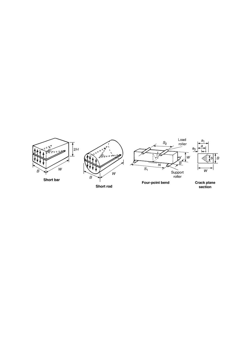
for stable crack growth. Chevron-notched specimens (Fig. 17) are used for determining
the fracture toughness of brittle materials that are difficult to fatigue precrack. Chevron
notches generate decreasing
K
-gradients at the start of precracking and may be machined
as part of the specimen, or they may be added just prior to testing using a thin diamond
wafering blade. The maximum slope of the chevron notch should be 45°. Precracking of
brittle materials should be performed under displacement control conditions, so that as
the crack extends, the load and the applied
K
decrease. Lastly, the loads should be
increased slowly from low levels due to the stochastic nature of crack initiation in these
materials. If initiation is especially difficult, compressive overloads may assist the
process. It is also helpful to monitor the initiation process with a method other than
optical observation, electric potential techniques and back face strain compliance.
Figure 17: Chevron notch in fracture mechanics specimens - the shaded area (b) is the crack area
Once precracking has been completed, an accurate optical measurement of the initial
crack length,
a
0
, must be made on both sides of the specimen to within 0.10 mm or
0.002
W
, or to within 0.25 mm for specimens of
W
> 127 mm. If the crack lengths on the
two surfaces differ by more than 0.25
B
, then the test will not be valid, because
K
-
calibration functions presume the existence of a straight crack front. Once the precrack
has been measured and side-to-side variation and distance from centerline have been
established, testing may start.
4.2.4. Equipment
Specimen size and geometry can also be influenced by laboratory equipment such as
the load frame, load cell, existing loading fixtures, testing environment, and even the
crack length measurement device, and available tools and equipment should be used.
Most modern mechanical testing laboratories exclusively use electrical servo
hydraulic load frames for FCGR investigations. Current controls and data acquisition
technology of hydraulic load-frames are more versatile than the electromechanical
systems used in previous years. When selecting a specimen geometry and size, one must
be aware of the load capacity of the actuator and load-frame. Loads that are too high
cannot be applied, and those that are too low cannot be controlled with the required
accuracy (±2%). In addition, the load cell to be used during testing must be able to