


 214 / 352

210
Maximal deformation of segment 2 due to mechanical loading in the first case, for
active upper part is
f
ma
x
= 4.02 cm and due to thermo mechanical loading is
f
max
= 8 cm,
and for active lower part is
f
max
= 3.86 cm and
f
ma
x
= 5.18 cm, respectively. Stress
distribution is presented in Fig. 4.3.
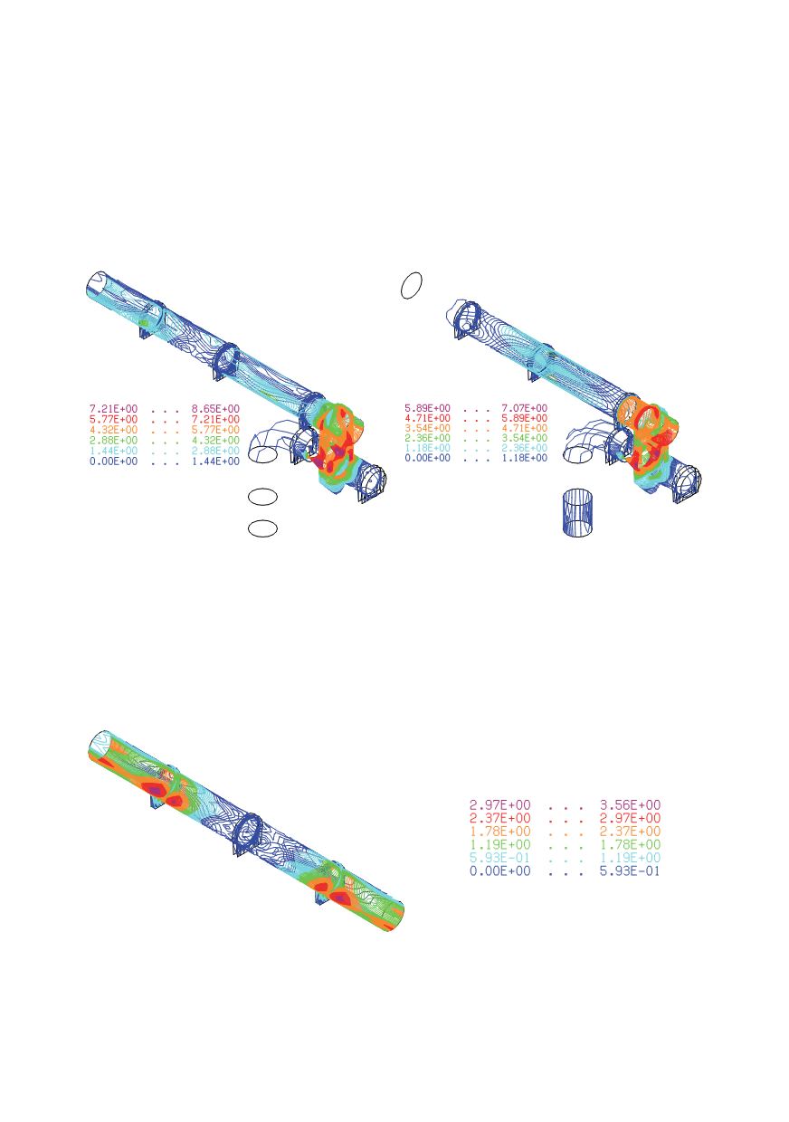
In both cases of working conditions and both cases of loading TD compensator is
disburden and HS compensator is loaded. Behaviour of segment 2 is satisfactory.
Active upper part, stress [kN/cm
2
]
Active lower part, stress [kN/cm
2
]
Figure 4.3: Stress in segment 2 due to thermo mechanical loading
Segment 4 – a part of the pipe-line of 17.6m between two fixed segments -
1400x6
Stress distribution in segment 4 due to thermo mechanical loading is shown in Fig. 4.4.
Stress [kN/cm
2
]
Figure 4.4: Stress distribution in segment 4 due to thermo mechanical loading