


 213 / 352

209
4. THERMOMECHANICAL CALCULATION OF THE GAS PIPELINE
The complete gas pipeline in the company RTB BOR is considered through selected
15 functional parts. Each part represents independent complex regarding loading.
Between two parts the functionless compensator is placed to accept transversal force.
The pipeline geometry and design conditions were taken of Mašinoprojekt KOPRING.
Following pipeline segments are considered: rapid gas line (segments 1-8), adsorb col-
lector (segments 9-11), oblique bypass 1 (segments 12-15), bypass 2 (segment 16).
Two cases of loading were analysed:
-
mechanical loading (weight of a construction, of a dust and of an isolation),
-
thermo mechanical loading (weight and design temperature).
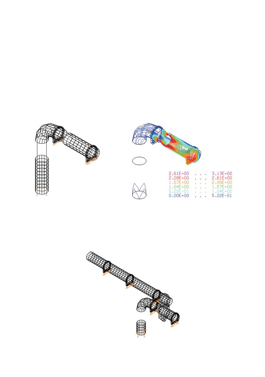
Segment 1 –
1400x6
Figure 4.1: Model and stress-field of segment 1 caused by thermo-mechanical loading [kN/cm
2
]
Maximal deformation of the segment 1, due to the mechanical loadingonly is
f
max
=1.14cm, and due to thermo mechanical loading is
f
max
= 4.54 cm.
Segment 2 – upper and lower entrance line (
1400x6)
Two cases of loading were considered, active upper andlower parts of gas pipeline.
Figure 4.2: Model and supports of segment 2