


 210 / 352

206
f
01
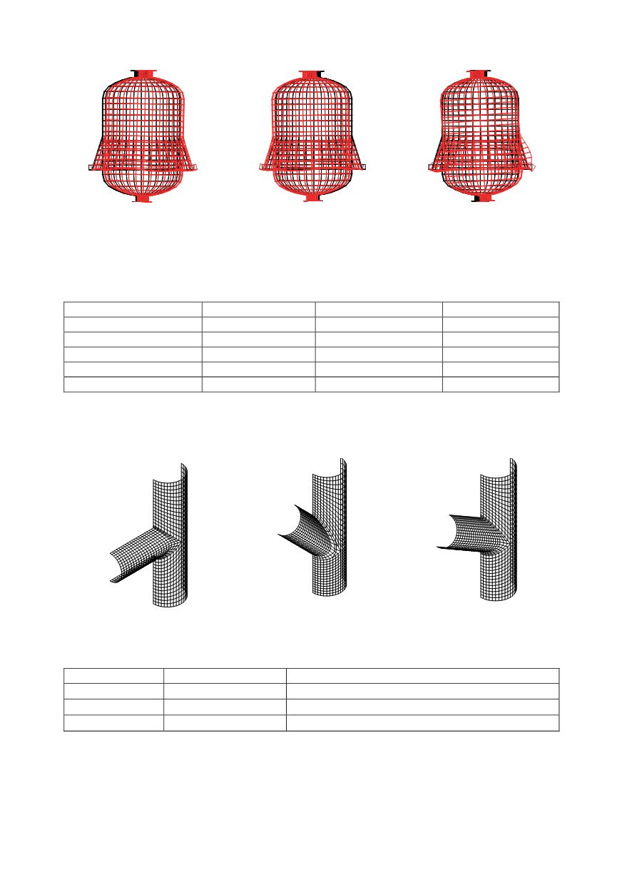
= 29,4 Hz, A = 0,009cm
f
02
= 29,5 Hz, A = 0,009 cm
f
03
= 42,4 Hz, A = 0,01 cm
Figure 2.6: Shape of first three modes of the reactor DC-303construction
In Table 2 eigen-frequencies of all reactor-constructions, obtained from dynamic finite
element analysis, are listed.
Table 2.2: Eigen-frequencies of the analysed reactors
Reactor
First mode
Second mode
Third mode
DC-301
20,6 Hz
42,5 Hz
64,1 Hz
DC-302
40 Hz
81,5 Hz
140,5 Hz
DC-303
29,4 Hz
29,5 Hz
42,4 Hz
DC-304
26,6 Hz
26,7 Hz
30 Hz
DC-401
17,9 Hz
18 Hz
50,3 Hz
3. CALCULATION OF THE STRENGHT OF THE CLAWS
FEM models of the claws of different shapes are presented in Fig. 3.1. As examples,
in Fig. 3.2 behaviour of the claw 90
o
is shown, in Figs. 3.3 and 3.4. of the claw 45
o.
Claw 90
o
Claw 45
o
Claw 60
o
Figure 3.1: FEM models of the claws
Table 3.1: Dimensions and pressures for calculation
Pressure
Dimensions
Claw 90
o
p=35 bar
pipe
267x12,5mm in pipe
317x14,2mm
Claw 45
o
p=25 bar
pipe
267x12,5mm in pipe
317x14,2mm
Claw 60
o
p=35 bar
pipe
267x12,5mm in pipe
317x14,2mm
3.1. Claw 90º
Nominal stress in section remote from gap, at the pressure 0.35 bar, is for:
o
Pipe
317x14.2 -
1
=
pR
1
/
t
1
= 0.35
15.85/1.42 = 3.91 kN/cm
2
,
o
Pipe
267x12.5 -
2
=
pR
2
/
t
2
= 0.35
13.35/1.25 = 3.74 kN/cm
2
.