


 220 / 352

216
Figure 6.5: The construction of the palette
Figure 6.6: Model of the palette in isometric
Figure 6.7: Loading and supports
Figure 6.8: Deformation of palette,
f
max
= 0.45 mm
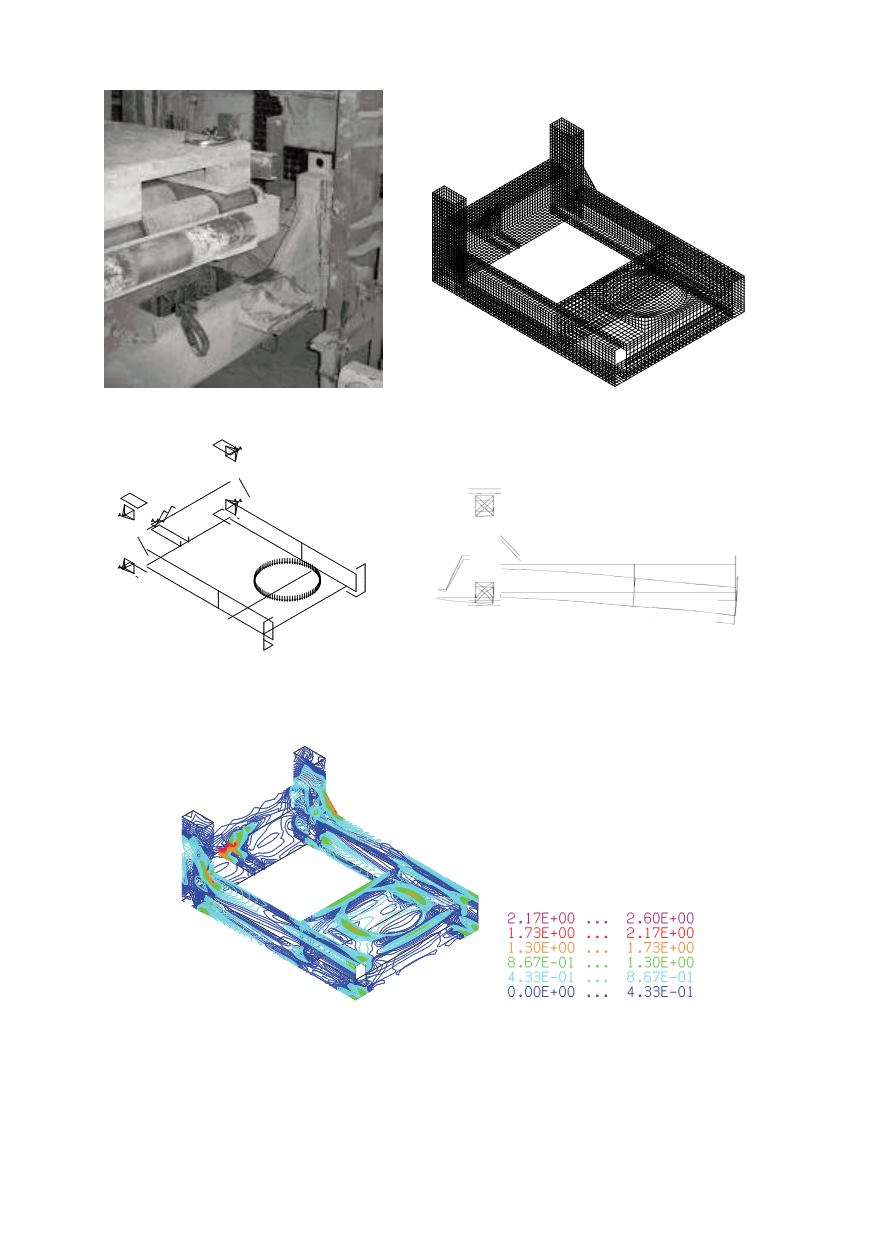
Figure 6.9: presents the palette stress field calculated by FEM for the loading of 10 kN.
Figure 6.9: Stress field in the palette
kN/cm
2
In the same case, the strain gauge was placed on one part of the palette surface. The
stress at this location is calculated to be 0.7 kN/cm
2
for loading of 10 kN. For maximum
load of 2 tons of cement, the stress on the strain gauge location would be 1.4 kN/cm
2
. The
maximum stress calculated was 26 kN/cm
2
, or in service 52 kN/cm
2
in diagonal elements.