


 205 / 352

201
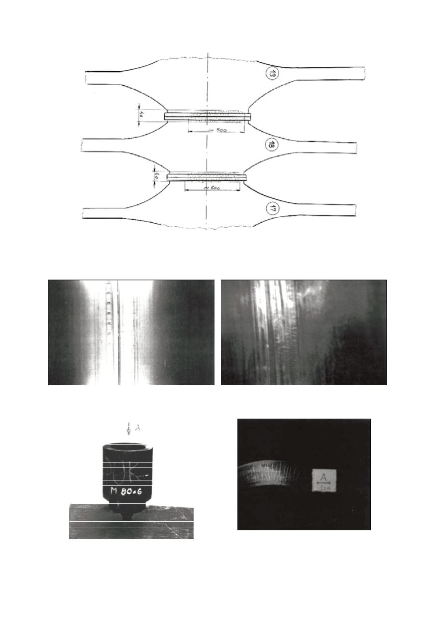
Figure 10: Distribution of discontinuities on discs 17, 18 and 19 of medium turbine rotor
Figure 11: Indication on discs 17 and 18
obtained by dye penetrant testing
Figure 12: Indication on discs 17 and 18
obtained by magnetic particles testing
Figure 13: Nut M 80X6
Figure 14: Indication on contact surface
obtained by magnetic particles testing