


 283 / 352

279
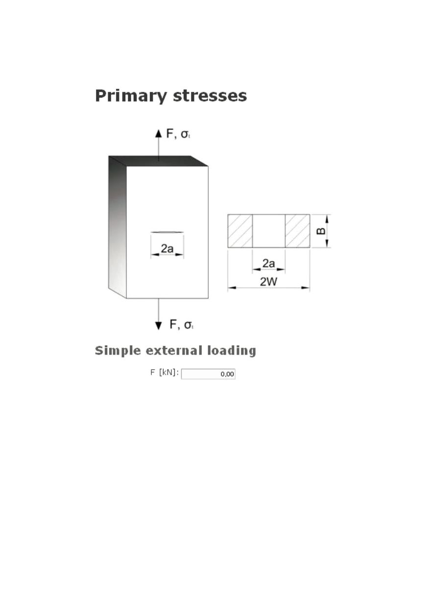
2.6. Material primary stresses
Here, the primary stresses in appropriate units are entered (Fig. 22).
Figure 22: Primary stresses form
2.7 Additional
2.7.1 Selectable boundary conditions
There are several boundary conditions available (an example is given in Fig. 23).
These options must not be left empty.
2.7.2 Calculation parameters
This dialog enables decision about the assessment with respect to the critical load or
critical crack (Critical value assessment), as shown in Fig. 24. The calculation is repeated
with only one parameter being changed, while other remains constant. Thus the loading
curve or the crack growth curve is drawn. This method enables to determine not only the
operating or nominal point, but also the critical or failure point. There are two parameters
that define the increase of selected value, these are steps for increasing the load or crack
length and the maximum load or crack length. The lower limit of the increasing parameter
is selected as a small positive number. The step for increasing the normalized load L
r
has