


 236 / 352

232
1 2 3 4 5 6
S1
S4
-2.00E+03
-1.50E+03
-1.00E+03
-5.00E+02
0.00E+00
5.00E+02
1.00E+03
1.50E+03
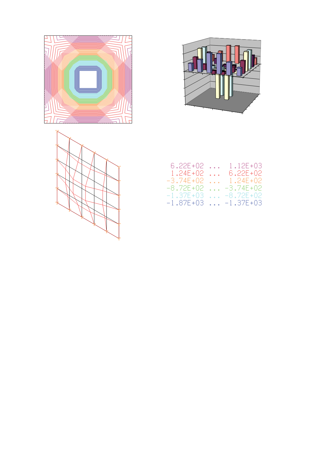
Figure 4: The square plate fixed along the each side. Distribution of potential and kinetic energy
increments, kNxcm, for initial and arbitrary modified plate is presented. First frequency of the
initial plate is
f
01
= 90.5 Hz, and for arbitrary modified plate
f
01
’
= 99.6 Hz.
The plate thickness was chosen as the design variable in the analysis, with the size 100
cm x 100 cm saved through the analysis. The effect of boundary condition was also
considered, for both hinged (Fig. 3) and fixed supports (Fig. 4). Calculation of eigen pairs
was performed using programme package KOMIPS /13/.
The modification consisted in arbitrary change of initial plate thickness uniformly by
10%. Potential and kinetic energies for modelled had been calculated using the Eqs. (1)
to (4) and the differences in increment determined, as presented in Fig. 3 and Fig. 4.
Based on obtained graphs for simple supported plate one can e concluded that elements
near corners of the plate have the biggest positive difference, and by increased stiffness
the dynamic behaviour is improved. The elements in the central part of the plate have the
greatest negative difference. It can be noticed that both, potential and kinetic energies
have the maximum values on this mode shape, what needs the more detailed reanalysis.
However it can be proved that by increasing stiffness (increasing section thickness), and
decreasing mass, the frequency will increase.
Analysing the fixed supported plate, stiffness should be increased on the elements
which correspond the middle part of the side of square (the purple part on the graph,
Fig.4), and at the central part of the plate, it is better to add elements with less mass and
of greater stiffness.