


 245 / 352

241
phase angle of the carrier wave, satellite ranging measurements derived from this proce-
dure are called "phase" data. It is to note that most low-cost GPS receivers used for navig-
ation applications produce only range data and positions derived from these measure-
ments. Higher cost surveying and geodetic GPS receivers produce range and phase data.
The higher accuracy of positioning is achieved by using Real-Time Kinematic (RTK).
RTK uses the satellite's carrier wave as its signal, not the messages contained within. In
practice, RTK systems use a single base station receiver and a number of mobile units
(rovers). The units calculate their relative position to millimeters, although their absolute
position is accurate only to the same accuracy as the position of the base station. The
typical nominal accuracy for these dual-frequency systems is 1 cm ± 2 parts-per-million
(ppm) horizontally and 2 cm ± 2 ppm vertically. RTK GPS is being used together with
sophisticated software to model the 3D position of a structure, and control the precise
placement of this structure.
This accuracy of GPS can be obtained using principles of
interferometry - a measurement technique based on the fact that two waveforms will
constructively or destructively interfere with each other if they arrive slightly out of
phase. It compares carrier signals using these effects rather than signals themselves.
Interferometric GPS is a technique which employs measurements of carrier phase diffe-
rence to provide highly accurate relative position measurements. The differencing inhe-
rent in the interferometric approach leads to cancellation of many errors including iono-
spheric and tropospheric errors, ephemeris errors, and the effects of selective availability.
Interferometric GPS uses the measurements at multiple antennae mounted on rigid base-
lines to provide orientation information. In the interferometric GPS technique, phase from
a satellite is measured at two or more receiving locations and differenced. The carrier
phase difference yields the distance between the two receiving sites projected along the
propagation direction. This is a triangulation, the measurement which uses angle measu-
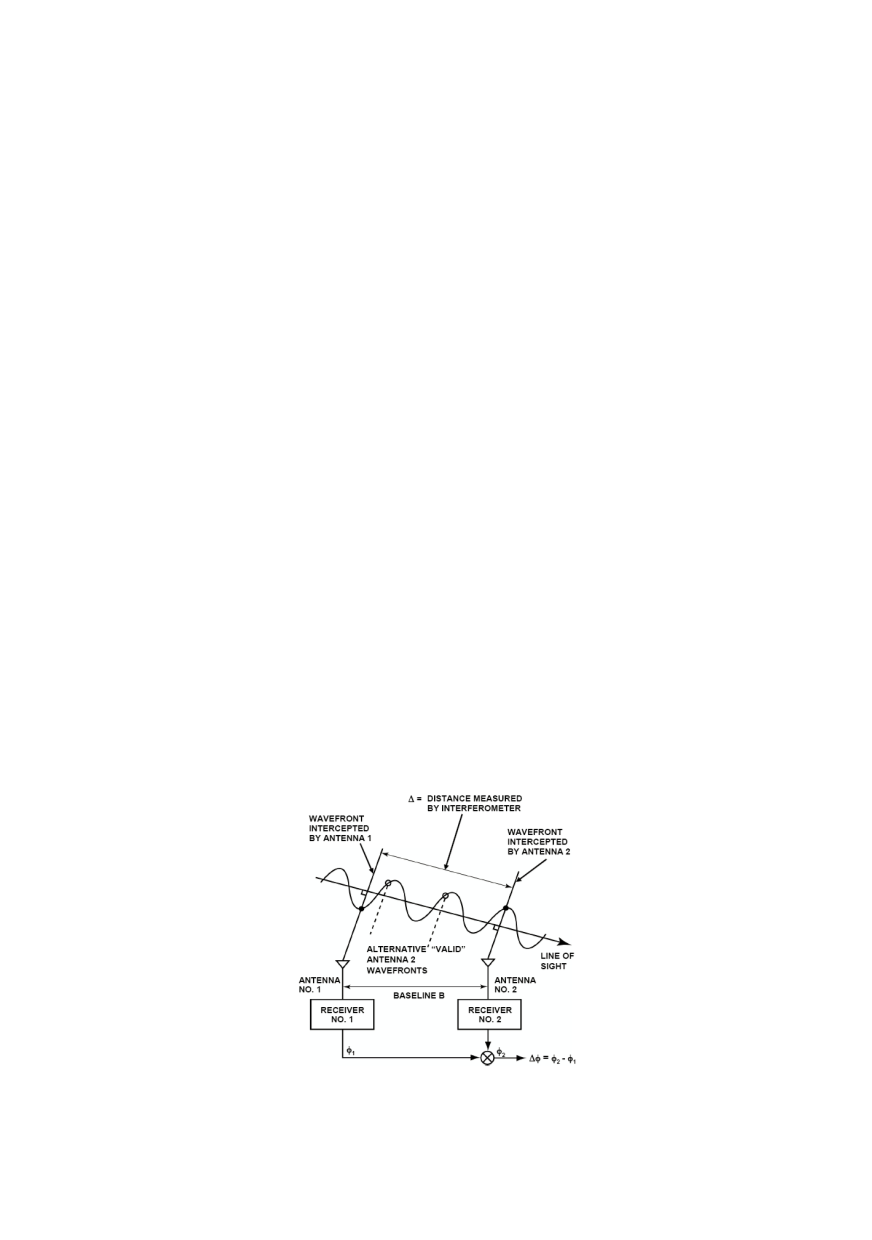
rements together with at least one known distance. Figure 3 represents a snapshot in time
of the transmitted wave’s amplitude from a single satellite. Receiver 1 intercepts a parti-
cular wavefront (determined by the perpendicular projection of the receiver 1 measure-
ment onto the line of sight). At this same instant in time, receiver 2 measures a different
wavefront (determined by perpendicular projection). The difference in phase between the
two wavefronts,
Δφ
, is a direct measure of the propagation distance.
Figure 3: Example of Simplified GPS Interferometry /2/